Rainbow Electronics MAX9755 User Manual
Page 14
MAX9750/MAX9751/MAX9755
2.6W Stereo Audio Power Amplifiers and
DirectDrive Headphone Amplifiers
14
______________________________________________________________________________________
parasitic bond wire and trace inductance. Although not
typically required, additional high-frequency ripple atten-
uation can be achieved by increasing the size of C2 (see
the Typical Application Circuit).
Headphone Sense Input (HPS)
The headphone sense input (HPS) monitors the head-
phone jack and automatically configures the device
based upon the voltage applied at HPS. A voltage of
less than 0.8V sets the device to speaker mode. A volt-
age of greater than 2V disables the bridge amplifiers
and enables the headphone amplifiers.
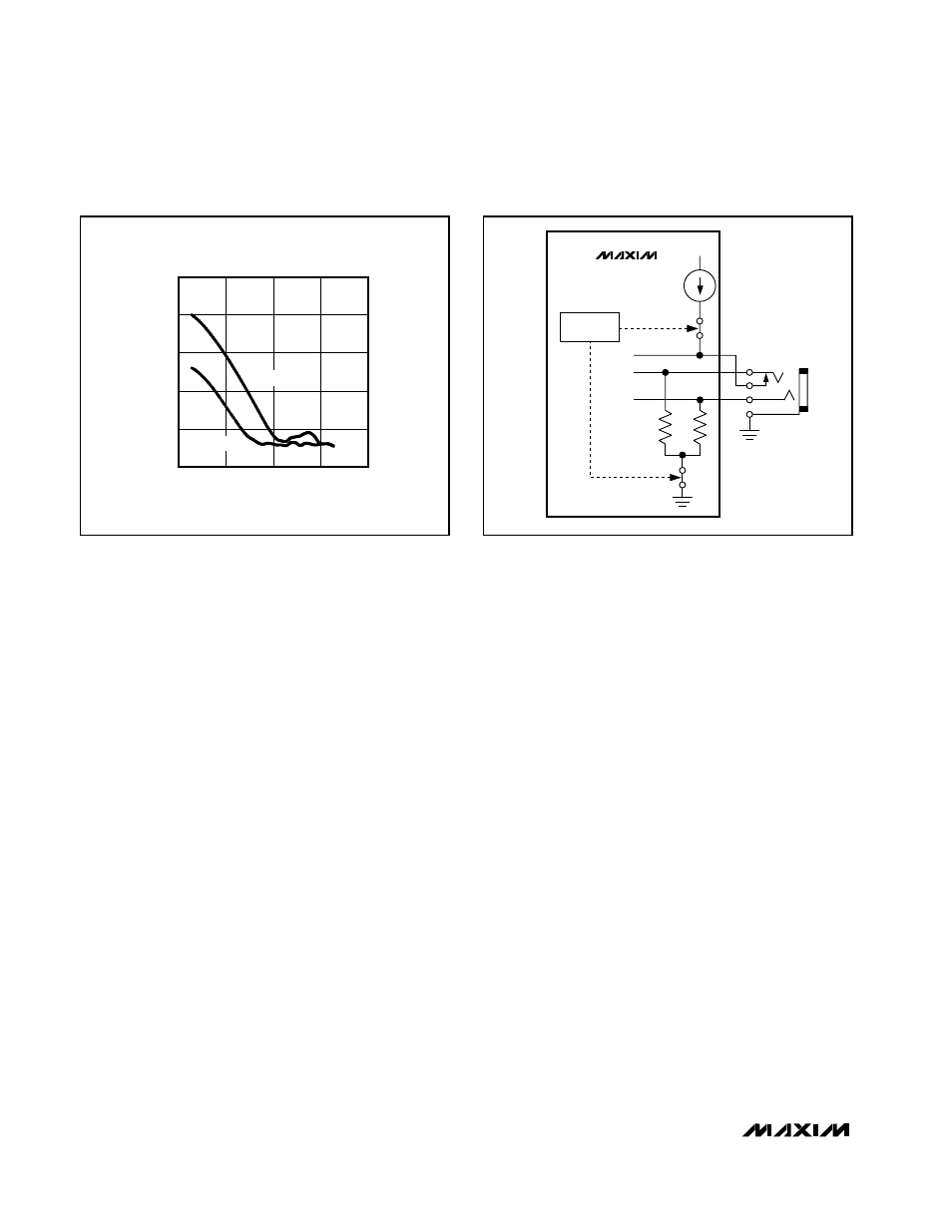
For automatic headphone detection, connect HPS to the
control pin of a 3-wire headphone jack as shown in
Figure 5. With no headphone present, the output imped-
ance of the headphone amplifier pulls HPS low. When a
headphone plug is inserted into the jack, the control pin
is disconnected from the tip contact and HPS is pulled
to V
DD
through a 10µA current source.
BIAS
The MAX9750/MAX9751/MAX9755 feature an internally
generated, power-supply independent, common-mode
bias voltage of 1.8V referenced to GND. BIAS provides
both click-and-pop suppression and sets the DC bias
level for the amplifiers. Choose the value of the bypass
capacitor as described in the BIAS Capacitor section.
No external load should be applied to BIAS. Any load
lowers the BIAS voltage, affecting the overall perfor-
mance of the device.
Gain Selection
MAX9750
The MAX9750 features an internally set, selectable gain.
The GAIN1 and GAIN2 inputs set the maximum gain of
the MAX9750 speaker and headphone amplifiers (Table
1). The gain of the device can vary based upon the volt-
age at VOL (see the Analog Volume Control section).
However, the maximum gain cannot be exceeded.
MAX9751/MAX9755
The gain of the MAX9751/MAX9755 is set by the GAIN
input. Driving GAIN high sets the gain of the speaker
amplifiers to 9dB and the gain of the headphone ampli-
fiers to 0dB. Driving GAIN low sets the gain of the
speaker amplifiers to 10.5dB, and the gain of the head-
phone amplifiers to 3dB (Table 2).
Analog Volume Control (VOL)
The MAX9750 features an analog volume control that
varies the gain of the device in 31 discrete steps based
upon the DC voltage applied to VOL. The input range of
V
VOL
is from 0 (full volume) to 0.858 x HPV
DD
(full mute),
with example step sizes shown in Table 3. Connect the
reference of the device driving VOL (Figure 6) to HPV
DD
.
Since the volume control ADC is ratiometric to HPV
DD
,
any changes in HPV
DD
are negated. The gain step sizes
are not constant; the step sizes are 0.5dB/step at the
upper extreme, 2dB/step in the midrange, and 4dB/step
at the lower extreme. Figure 7 shows the transfer function
of the volume control for a 3.3V supply.
ADDITIONAL THD+N DUE
TO DC-BLOCKING CAPACITORS
FREQUENCY (Hz)
THD+N (%)
10k
1k
100
0.001
0.01
0.1
1
10
0.0001
10
100k
TANTALUM
ALUM/ELEC
Figure 4. Distortion Contributed by DC-Blocking Capacitors
MAX9750/
MAX9751/
MAX9755
10µA
1kΩ
1kΩ
20
14
13
V
DD
HPS
HPOUTL
HPOUTR
SHUTDOWN
CONTROL
Figure 5. HPS Configuration