Pin configuration – Rainbow Electronics MAX12553 User Manual
Page 27
MAX12553
14-Bit, 65Msps, 3.3V ADC
______________________________________________________________________________________
27
actual sampling instant. Aperture delay (t
AD
) is the time
defined between the falling edge of the sampling clock
and the instant when an actual sample is taken (Figure 4).
Aperture Jitter
Figure 4 depicts the aperture jitter (t
AJ
), which is the
sample-to-sample variation in the aperture delay.
Output Noise (n
OUT
)
The output noise (n
OUT
) parameter is similar to the ther-
mal + quantization noise parameter and is an indication
of the ADC’s overall noise performance.
No fundamental input tone is used to test for n
OUT
; INP,
INN, and COM are connected together and 1024k data
points collected. n
OUT
is computed by taking the RMS
value of the collected data points.
Overdrive Recovery Time
Overdrive recovery time is the time required for the
ADC to recover from an input transient that exceeds the
full-scale limits. The MAX12553 specifies overdrive
recovery time using an input transient that exceeds the
full-scale limits by ±10%.
REFP
1
REFN
2
COM
3
GND
4
INP
5
INN
6
GND
7
DCE
8
CLKN
9
CLKP
10
D2
30
D3
29
D4
28
D5
27
D6
26
D7
25
D8
24
D9
23
D10
22
D11
21
40
REFIN
39
REFOUT
38
PD
37
V
DD
36
GND
35
OV
DD
34
DAV
33
D0
32
D1
31
CLKTYP
11
V
DD
12
V
DD
13
V
DD
14
V
DD
15
GND
16
OV
DD
17
DOR
18
D13
19
D12
20
G/T
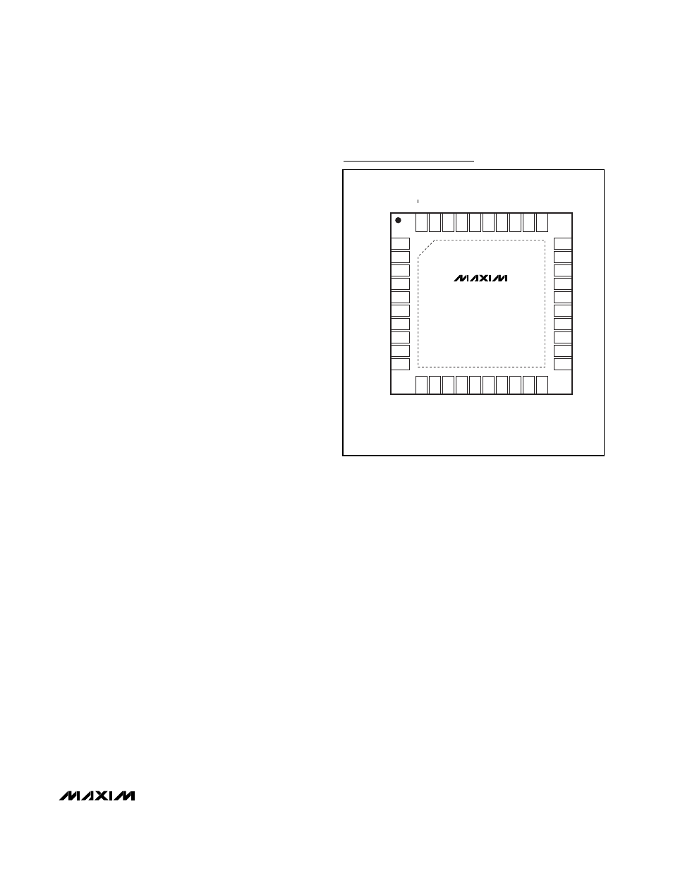
TOP VIEW
MAX12553
EXPOSED PADDLE (GND)
THIN QFN
6mm x 6mm x 0.8mm
Pin Configuration