Applications information – Rainbow Electronics MAX14770E User Manual
Page 13
High-ESD Profibus RS-485 Transceiver
MAX14770E
______________________________________________________________________________________ 13
Thermal-Shutdown Protection
The MAX14770E features thermal-shutdown circuitry.
The internal switch turns off when the junction tempera-
ture exceeds +160NC (typ) and immediately goes into a
fault mode. The device exits thermal shutdown after the
junction temperature cools by 15NC (typ).
Applications Information
128 Transceivers on the Bus
The standard RS-485 receiver input impedance is one
unit load, and a standard driver can drive up to 32 unit
loads. The MAX14770E transceiver has a 1/4 unit load
receiver, which allows up to 128 transceivers connected
in parallel on one communication line. Connect any com-
bination of these devices, and/or other RS-485 devices,
for a maximum of 32 unit loads to the line.
Low-Power Shutdown Mode
Low-power shutdown mode is initiated by bringing both
RE high and DE low. In shutdown, the devices draw only
15FA (max) of supply current. RE and DE can be driven
simultaneously; the devices are guaranteed not to enter
shutdown if RE is high and DE is low for less than 50ns. If
the inputs are in this state for at least 800ns, the devices
are guaranteed to enter shutdown.
Driver Output Protection
Two mechanisms prevent excessive output current and
power dissipation caused by faults or by bus conten-
tion. The first, a foldback current limit on the output
stage, provides immediate protection against short cir-
cuits over the whole common-mode voltage range (see
the Typical Operating Characteristics). The second, a
thermal-shutdown circuit, forces the driver outputs into
a high-impedance state if the die temperature exceeds
+160NC (typ).
Typical Application
The MAX14770E transceivers are designed for bidirectional
data communications on multipoint bus transmission lines.
Figure 12 shows a typical network applications circuit. To
minimize reflections, the line should be terminated at both
ends in its characteristic impedance, and stub lengths off
the main line should be kept as short as possible.
Profibus Termination
The MAX14770E is designed for driving PROFIBUS-DP
termination networks. With a worst-case loading of two
termination networks with 220I termination impedance
and 390I pullups/pulldowns, the drivers can drive
V(
A - B)
> 2.1V output.
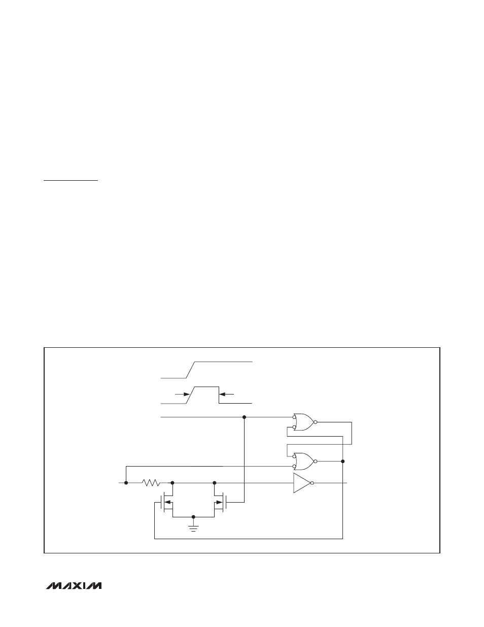
Figure
11. Simplified Structure of the Driver Enable Pin (DE)
V
CC
TIMER
DE
TIMER
5.6kI
15Fs
100FA
1mA
M2
M1
DRIVER
ENABLE
(HOT SWAP)