Pin configurations pin description – Rainbow Electronics MAX14770E User Manual
Page 11
High-ESD Profibus RS-485 Transceiver
MAX14770E
______________________________________________________________________________________ 11
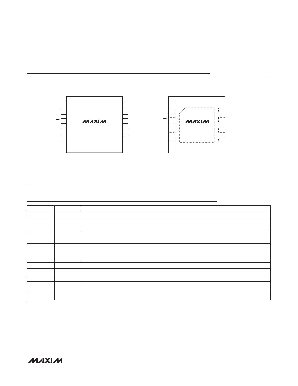
Pin Configurations
Pin Description
PIN
NAME
FUNCTION
1
RO
Receiver Output. When RE is low and (A - B) R -50mV, RO is high; if (A - B) P -200mV, RO is low.
2
RE
Receiver Enable. Drive RE low to enable RO; RO is high impedance when RE is high. Drive RE
high and DE low to enter low-power shutdown mode.
3
DE
Driver Enable. Drive DE high to enable driver output. The driver outputs are high impedance when
DE is low. Drive RE high and DE low to enter low-power shutdown mode.
4
DI
Driver Input. With DE high, a low on DI forces the noninverting output, A, low and the inverting out-
put, B, high. Similarly, a high on DI forces the noninverting output, A, high and the inverting output,
B, low.
5
GND
Ground
6
A
Noninverting Receiver Input and Noninverting Driver Output
7
B
Inverting Receiver Input and Inverting Driver Output
8
V
CC
Positive Supply. Bypass V
CC
to GND with a 0.1FF ceramic capacitor as close as possible to the
device.
—
EP
Exposed Pad (TDFN Only). Connect EP to GND.
MAX14770E
+
TOP VIEW
A
GND
8
7
V
CC
B
SO
6
5
DE
DI
1
2
RO
3
4
RE
1
+
4
3
8
6
5
V
CC
MAX14770E
2
7
B
A
GND
DE
RO
DI
TDFN
(3mm × 3mm)
*CONNECT EXPOSED PAD TO GND.
*EP
RE