Rainbow Electronics MAX16831 User Manual
Page 11
Reference Voltage Output
The MAX16831 includes a 5% accurate 3V (typ)
buffered reference output, REF. REF is a push-pull out-
put capable of sourcing/sinking 100µA of current and
can drive a maximum load capacitance of 100pF.
Connect REF to DIM through a resistive voltage-divider
to supply an analog signal for dimming. See the
Dimming Input (DIM)
section.
Dimming MOSFET Driver (DDR)
The MAX16831 requires an external n-channel
MOSFET for PWM dimming. Connect the MOSFET to
the output of the DDR dimming driver, DGT, for normal
operation. V
DGT
swings between V
LO
and V
CLMP
. The
DDR dimming driver is capable of sinking or sourcing
up to 20mA of current. The average current required to
drive the dimming MOSFET (I
DRIVE_DIM
) depends on
the MOSFET’s total gate charge (Q
G_DIM
) and the dim-
ming frequency of the converter, f
DIM
. Use the follow-
ing equation to calculate the average gate drive current
for the n-channel dimming FET.
I
DRIVE_DIM
= Q
G_DIM
x f
DIM
n-Channel MOSFET Switch Driver (DRV)
The MAX16831 drives an external n-channel MOSFET.
Use an external supply or connect REG2 to DRI to
power the MOSFET driver. The driver output, V
DRV
,
swings between ground and V
DRI
. Ensure that V
DRI
remains below the absolute maximum V
GS
rating of the
external MOSFET. DRV is capable of sinking 2.5A or
sourcing 1.4A of peak current, allowing the MAX16831
to switch MOSFETs in high-power applications. The
average current sourced to drive the external MOSFET
depends on the total gate charge (Q
G
) and operating
frequency of the converter, f
SW
. The power dissipation
in the MAX16831 is a function of the average output
drive current (I
DRIVE
). Use the following equations to
calculate the power dissipation in the gate driver sec-
tion of the MAX16831 due to I
DRIVE
:
I
DRIVE
= Q
G
x f
SW
P
D
= (I
DRIVE
+ I
CC
) x V
DRI
where V
DRI
is the supply voltage to the gate driver and
I
CC
is the operating supply current. I
DRIVE
should not
exceed 20mA.
Dimming Input (DIM)
The dimming input, DIM, functions with either analog or
PWM control signals. Once the internal pulse detector
detects three successive edges of a PWM signal with a
frequency between 80Hz and 2kHz, the MAX16831 syn-
chronizes to the external signal and pulse-width-modu-
lates the LED current at the external DIM input frequency
with the same duty cycle as the DIM input. If an analog
control signal is applied to DIM, the MAX16831 com-
pares the DC input to an internally generated 200Hz
ramp to pulse-width-modulate the LED current (f
DIM
=
200Hz). The output current duty cycle is linearly
adjustable from 0 to 100% (0.2V < V
DIM
< 2.8V).
Use the following formula to calculate the voltage, V
DIM
,
necessary for a given output-current duty cycle, D:
V
DIM
= (D x 2.6) + 0.2V
where V
DIM
is the voltage applied to DIM in volts.
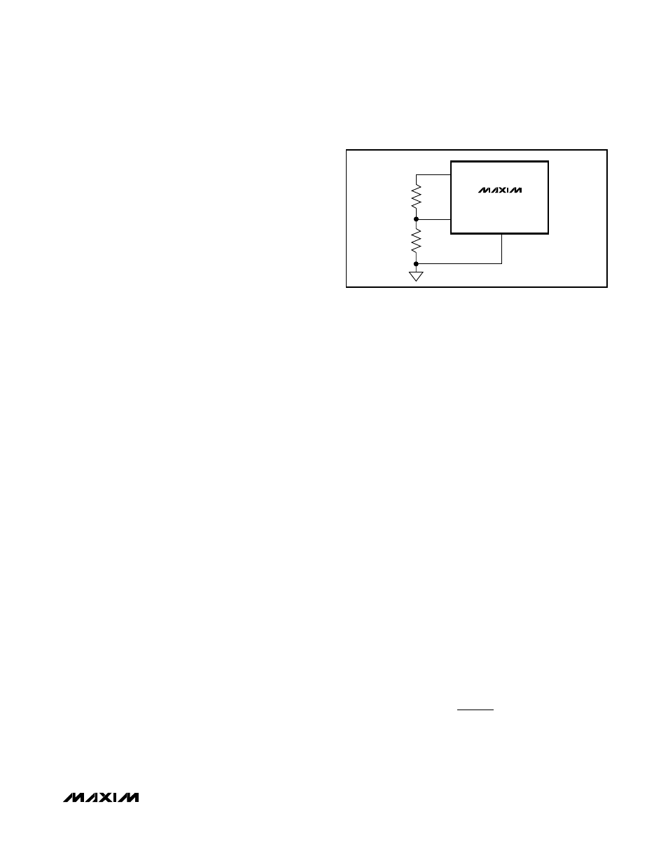
Connect DIM to REF through a resistive voltage-divider
to apply a DC DIM control signal (Figure 2). Use the
required dimming input voltage, V
DIM
, calculated
above and select appropriate resistor values using the
following equation:
R
4
= R
3
x V
DIM
/ (V
REF
- V
DIM
)
where V
REF
is the 3V reference output voltage and
30kΩ ≤ R
3
+ R
4
≤ 150kΩ.
For proper operation at startup or after toggling ENABLE,
the controller needs three clock edges or an analog volt-
age greater than 0.3V on the DIM input.
Oscillator, Clock, and Synchronization
The MAX16831 is capable of stand-alone operation or
synchronizing to an external clock, and driving external
devices in SYNC mode. For stand-alone operation, pro-
gram the switching frequency by connecting a single
external resistor, R
T
, between RTSYNC and ground.
Select the switching frequency, f
SW
, from 125kHz to
600kHz and calculate R
T
using the following formula:
where the switching frequency is in kHz and RT is in kΩ.
The MAX16831 is also capable of synchronizing to an
external clock signal ranging from 125kHz to 600kHz.
R
kHz
f
k
T
SW
=
×
500
25
Ω
MAX16831
High-Voltage, High-Power LED Driver with
Analog and PWM Dimming Control
______________________________________________________________________________________
11
MAX16831
REF
AGND
R
3
R
4
DIM
Figure 2. Creating a DIM Input Signal from REF