Test circuits and waveforms (continued) – Rainbow Electronics MAX13486E User Manual
Page 9
MAX13485E/MAX13486E
Half-Duplex RS-485/RS-422 Transceivers in µDFN
_______________________________________________________________________________________
9
1.5V
1.5V
A, B
0
0
OUTPUT NORMALLY LOW
DE
OUTPUT NORMALLY HIGH
t
DZL(SHDN)
,t
DZL
t
DZH(SHDN)
,t
DZH
t
DLZ
t
DHZ
2.3V
2.3V
V
OL
+ 0.5V
V
OH
+ 0.5V
A, B
V
OL
V
CC
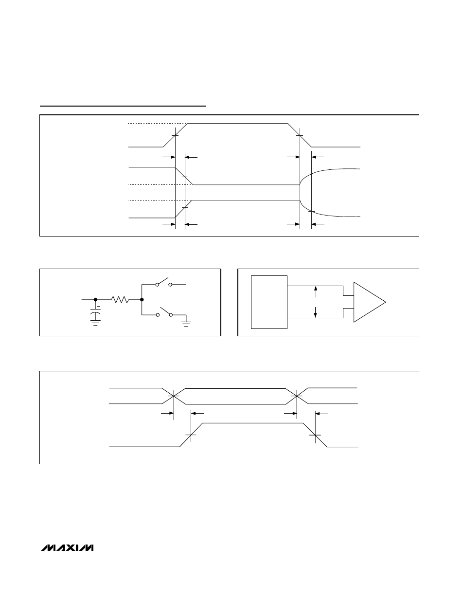
Figure 4. Driver Enable and Disable Times
ATE
V
ID
A
B
R
RECEIVER
OUTPUT
Figure 6. Receiver Propagation Delay Test Circuit
OUTPUT
UNDER TEST
500
Ω
S1
S2
V
CC
C
L
Figure 5. Driver-Enable and -Disable-Timing Test Load
1.5V
1.5V
1V
-1V
f = 1MHz, t
LH
≤ 3ns, t
HL
≤ 3ns
t
RPHL
t
RPLH
V
OH
V
OL
RO
A
B
t
RSKEW
= |t
RPHL
- t
RPLH
|
Figure 7. Receiver Propagation Delays
Test Circuits and Waveforms (continued)
See also other documents in the category Rainbow Electronics Control panel:
- MAX16840 (1 page)
- MAX9258 (54 pages)
- MAX66140 (21 pages)
- MAX9393 (14 pages)
- MAX66040 (25 pages)
- MAX6981 (1 page)
- MAX6965 (23 pages)
- MAX66100 (16 pages)
- MAX9135 (19 pages)
- MAX66020 (25 pages)
- MAX17127 (22 pages)
- MAX13175E (38 pages)
- MAX16820 (10 pages)
- MAX13237E (16 pages)
- MAX13483E (19 pages)
- MAX13362 (14 pages)
- MAX7311 (17 pages)
- MAX8759 (31 pages)
- SCAN92LV090 (13 pages)
- MAX6973 (23 pages)
- MAX13047E (14 pages)
- MAX16831 (20 pages)
- MAX14770E (15 pages)
- MAX11835 (1 page)
- MAX9621 (14 pages)
- MAX9217 (16 pages)
- MAX16841 (18 pages)
- MAX16834 (22 pages)
- MAX7315 (27 pages)
- MAX8645Y (15 pages)
- MAX6975 (23 pages)
- MAX6971 (12 pages)
- MAX3028 (21 pages)
- MAX9395 (13 pages)
- MAX7313 (27 pages)
- MAX6970 (1 page)
- MAX4821 (13 pages)
- MAX4895E (8 pages)
- MAX16823 (13 pages)
- MAX6963 (34 pages)
- MAX9216 (17 pages)
- MAX66000 (21 pages)
- MAX66120 (24 pages)
- MAX13223E (11 pages)