Pin description, Function tables – Rainbow Electronics MAX13486E User Manual
Page 10
MAX13485E/MAX13486E
Half-Duplex RS-485/RS-422 Transceivers in µDFN
10
______________________________________________________________________
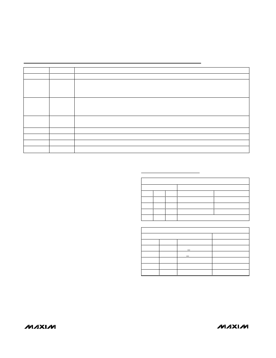
Pin Description
PIN
NAME
FUNCTION
1
RO
Receiver Output
2
RE
Receiver Output Enable. Drive RE low to enable RO. RO is high impedance when RE is high. Drive
RE high and DE low to enter low-power shutdown mode. RE is a hot-swap input (see the Hot-Swap
Capability section for more details).
3
DE
Driver Output Enable. Drive DE high to enable the driver outputs. These outputs are high-impedance
when DE is low. Drive RE high and DE low to enter low-power shutdown mode. DE is a hot-swap input
(see the Hot-Swap Capability section for more details).
4
DI
Driver Input. Drive DI low to force noninverting output low and inverting output high. Drive DI high to
force noninverting output high and inverting output low (see the Function Tables).
5
GND
Ground
6
A
Noninverting Receiver Input and Noninverting Driver Output
7
B
Inverting Receiver Input and Inverting Driver Output
8
V
CC
Positive Supply, V
CC
= +5V ±5%. Bypass V
CC
to GND with a 0.1µF capacitor.
TRANSMITTING
INPUT
OUTPUT
RE
DE
DI
B
A
X
1
1
0
1
X
1
0
1
0
0
0
X
HIGH IMPEDANCE
HIGH IMPEDANCE
1
0
X
SHUTDOWN
RECEIVING
INPUT
OUTPUT
RE
DE
A-B
RO
0
X
> -50mV
1
0
X
<
-200mV
0
0
X
OPEN/SHORT
1
1
1
X
HIGH IMPEDANCE
1
0
X
SHUTDOWN
Function Tables
X = Don’t care, shutdown mode, driver, and receiver outputs
are in high impedance.