Th7804a – Rainbow Electronics TH7804A User Manual
Page 8
8
TH7804A
1989A–IMAGE–05/02
Note:
1. Drain supply current I
DD
decreases from 10 mA to 8 mA typically when internal sampling clock is disabled.
Insertion of a serial resistor (typically 100
Ω) at the driver output avoids spurious negative transients.
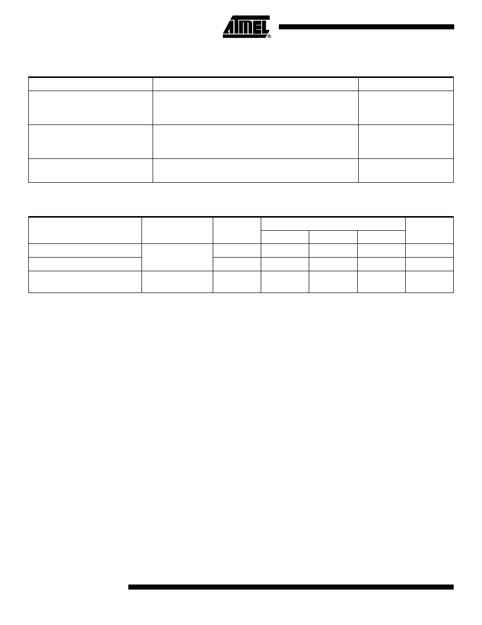
Table 6. Selection of Operating Modes
Option
Implementation
Remarks
No Sampling
Φ
ECHA
(2) and
Φ
ECHB
(22) connected to V
DD
S
Φ
ECHA
(3) and S
Φ
ECHB
(21) unconnected
V
INH
(19) connected to V
DD
Sampling by External Clocks
Sampling clocks connected to
Φ
ECHA
Φ
ECHB
S
Φ
ECHA
and S
Φ
ECHB
unconnected
V
INH
(19) connected to V
DD
see Figure 5 for
sampling clock timing
Reset Control by External Clocks
Ext.
Φ
RA
on
Φ
RA
(4) input
Ext.
Φ
RB
on
Φ
RB
(18)
see Figure 4 for
reset clock timing
Table 7. External
Φ
RA
,
Φ
RB
,
Φ
ECHA
,
Φ
ECHB
Clock Characteristics
Parameter
Symbol
Logic
Values
Unit
Min.
Typ.
Max.
External Reset Clock
Φ
RA
,
Φ
RB
Φ
ECHA
,
Φ
ECHB
High
12
12.5
13
V
Sampling Clocks
Low
0.0
0.4
0.6
V
Reset and Sampling Clock
Capacitance
C
Φ
RA
, C
Φ
RB
C
Φ
ECHA
, C
Φ
ECHB
10
15
pF