Pin description – Rainbow Electronics MAX5098A User Manual
Page 11
MAX5098A
Dual, 2.2MHz, Automotive Buck or Boost
Converter with 80V Load-Dump Protection
______________________________________________________________________________________
11
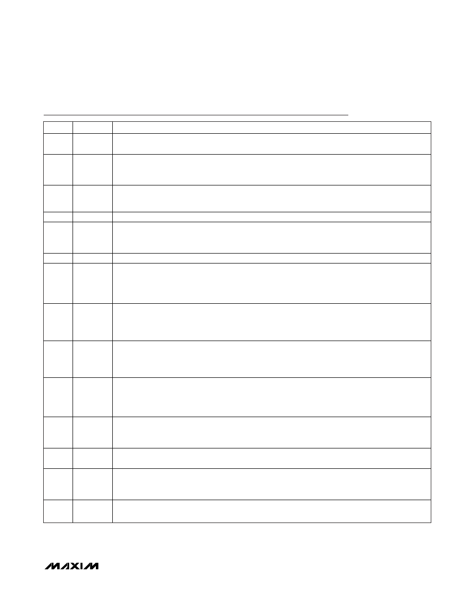
Pin Description
PIN
NAME
FUNCTION
1, 32
SOURCE2
Converter 2 Internal MOSFET Source Connection. For buck converter operation, connect SOURCE2 to the
switched side of the inductor. For boost operation, connect SOURCE2 to PGND_ (Figure 6).
2, 3
DRAIN2
Converter 2 Internal MOSFET Drain Connection. For buck converter operation, use the MOSFET as a high-
side switch and connect DRAIN2 to the DC-DC converters supply input rail. For boost converter operation,
use the MOSFET as a low-side switch and connect DRAIN2 to the inductor and diode junction (Figure 6).
4
PGOOD2
Converter 2 Open-Drain Power-Good Output. PGOOD2 goes low when converter 2’s output falls below
92.5% of its set regulation voltage. Use PGOOD2 and EN1 to sequence the converters. Converter 2 starts
first.
5
EN2
Converter 2 Active-High Enable Input. Connect to V
L
for always-on operation.
6
FB2
Converter 2 Feedback Input. Connect FB2 to a resistive divider between converter 2’s output and SGND to
adjust the output voltage. To set the output voltage below 0.8V, connect FB2 to a resistive voltage-divider
from BYPASS to regulator 2’s output (Figure 3). See the Setting the Output Voltage section.
7
COMP2
Converter 2 Internal Transconductance Amplifier Output. See the Compensation section.
8
OSC
Oscillator Frequency Set Input. Connect a resistor from OSC to SGND (R
OSC
) to set the switching frequency
(see the Setting the Switching Frequency section). Set R
OSC
for an oscillator frequency equal to the SYNC
input frequency when using external synchronization. R
OSC
is still required when an external clock is
connected to the SYNC input. See the Synchronization (SYNC)/Clock Output (CKO) section.
9
SYNC
External Clock Synchronization Input. Connect SYNC to a 400kHz to 4400kHz clock to synchronize the
switching frequency with the system clock. Each converter frequency is 1/2 of the frequency applied to
SYNC (FSEL_1 = V
L
). For FSEL_1 = SGND, the switching frequency of converter 1 becomes 1/4 of the
SYNC frequency. Connect SYNC to SGND when not used.
10
GATE
Gate Drive Output. Connect to the gate of the external n-channel load-dump protection MOSFET. GATE =
IN_HIGH + 9V (typ) with IN_HIGH = 12V. GATE pulls to IN_HIGH by an internal n-channel MOSFET when V+
raises 2V above IN_HIGH. Leave gate unconnected if the load-dump protection is not used (MOSFET not
installed).
11
ON/OFF
n-Channel Switch Enable Input. Drive ON/OFF high for normal operation. Drive ON/OFF low to turn off the
external n-channel load-dump protection MOSFET and reduce the supply current to 7µA (typ). When
ON/OFF is driven low, both DC-DC converters are disabled and the PGOOD_ outputs are driven low.
Connect to V+ if the external load-dump protection is not used (MOSFET not installed).
12
IN_HIGH
Startup Input. IN_HIGH is protected by internally clamping to 21V (max). Connect a resistor (4k
Ω max) from
IN_HIGH to the drain of the protection switch. Bypass IN_HIGH with a 4.7µF electrolytic or 1µF minimum
ceramic capacitor. Connect to V+ if the external load-dump protection is not used (MOSFET not installed).
13
V+
Input Supply Voltage. V+ can range from 5.2V to 19V. Connect V+, IN_HIGH, and V
L
together for 4.5V to
5.5V input operation. Bypass V+ to SGND with a 1µF minimum ceramic capacitor.
14
V
L
Internal Regulator Output. The V
L
regulator is used to supply the drive current at input VDRV. When driving
VDRV, use an RC lowpass filter to decouple switching noise from VDRV to the V
L
regulator (see the Typical
Application Circuit). Bypass V
L
to SGND with a 4.7µF minimum ceramic capacitor.
15
SGND
Signal Ground. Connect SGND to exposed pad and to the board signal ground plane. Connect the board
signal ground and power ground planes together at a single point.