Applications information, Table 7. channel-selection register – Rainbow Electronics MAX7473 User Manual
Page 15
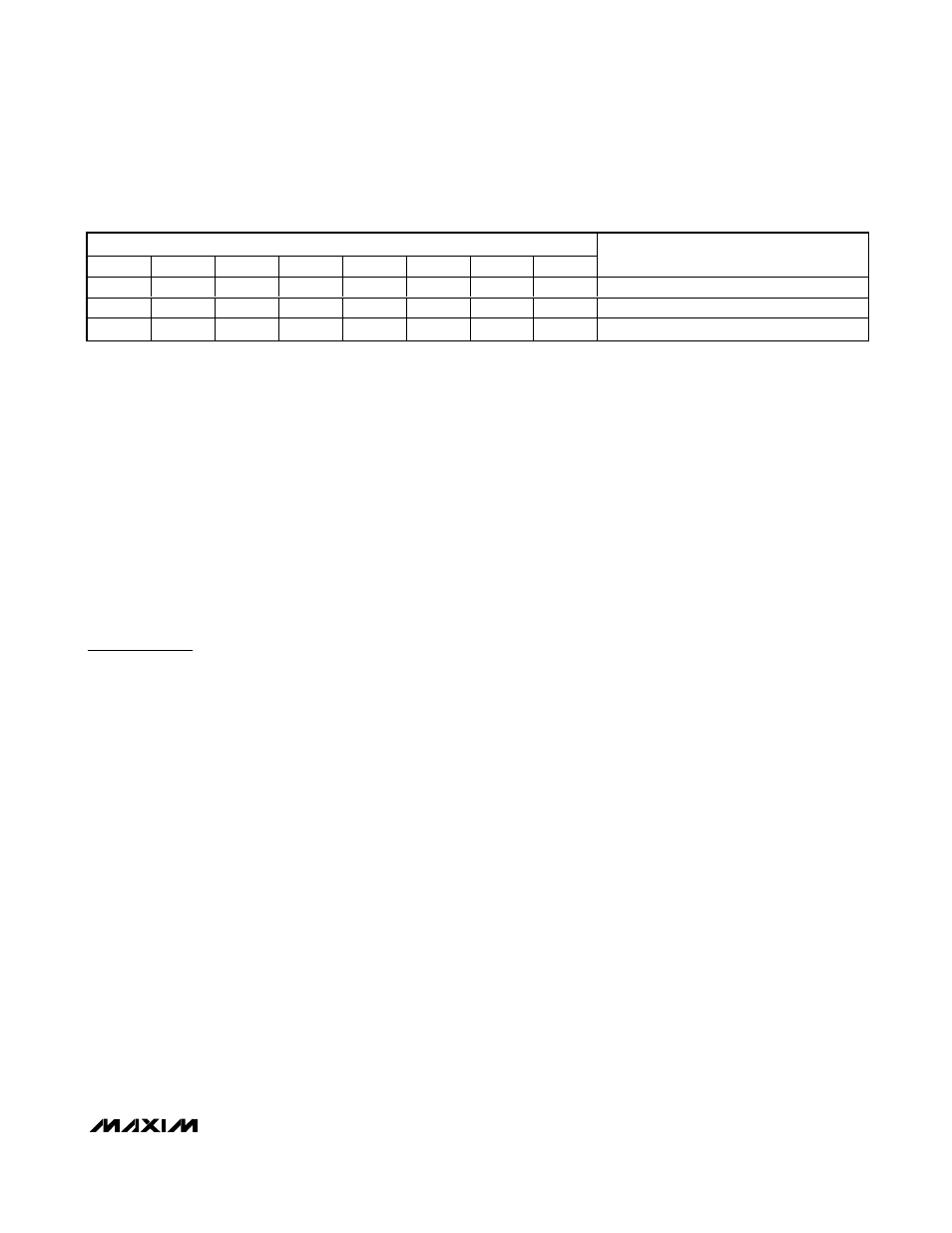
Channel-Selection Register
The MAX7472/MAX7473 store channel selection in an
8-bit register that can be read back by the master. The
individual bits of the Channel Selection register are
summarized in Table 7. The power-on default selects
channel A.
I
2
C Compatibility
The MAX7472/MAX7473 are compatible with existing
I
2
C systems supporting standard I
2
C 8-bit communica-
tions. The general call address is ignored, and CBUS
formats are not supported. The devices’ address is
compatible with 7-bit I
2
C addressing protocol only.
Ten-bit address formats are not supported.
Applications Information
Input Considerations
Use 0.1µF ceramic capacitors to AC-couple the inputs.
The input cannot be DC-coupled. The internal clamp
circuit stores a DC voltage across the input capacitors
to obtain the appropriate output DC voltage level.
Increasing the value of these capacitors to improve
line-time distortion is not necessary due to the extreme-
ly low input leakage current yielding a very low line-time
distortion performance.
The MAX7472/MAX7473 provide a high input imped-
ance to allow a nonzero source impedance to be used
such as when the input is connected directly to a back-
matched video cable, ensuring the external resistance
determines the termination impedance.
Output Considerations
The MAX7472/MAX7473 outputs can be DC- or AC-
coupled. The MAX7473, with +6dB gain, is typically
connected to a 75Ω series back-match resistor fol-
lowed by the video cable. Because of the inherent
divide-by-two of this configuration, the blanking level of
the video signal is always less than 1V, which complies
with digital TV requirements.
The MAX7472, with 0dB gain, is typically connected to
an ADC or video decoder. This can be a DC or AC con-
nection. If a DC connection is used, ensure that the DC
input requirements of the ADC or video decoder are
compatible.
When using an AC connection, choose an AC-coupling
capacitor value that ensures that the lowest frequency
content in the video signal is passed and the line-time
distortion is kept within desired limits. The selection of
this value is a function of the input impedance and more
importantly, the input leakage of the circuit being driven.
Use a video clamp to reestablish the DC level if not
already included in the subsequent circuit.
The outputs of the MAX7472/MAX7473 are fully protect-
ed against short-circuit conditions either to ground or to
the positive supply of the device.
MAX7472/MAX7473
HDTV Anti-Aliasing Filters with Triple-Input Mux
______________________________________________________________________________________
15
Table 7. Channel-Selection Register
CHANNEL-SELECTION REGISTER
CS7
CS6
CS5
CS4
CS3
CS2
CS1
CS0
DESCRIPTION
0
0
X
X
X
X
X
X
Channel A selected (default).
0
1
X
X
X
X
X
X
Channel B selected.
1
0
X
X
X
X
X
X
Channel C selected.
X = Don’t care.