Read cycle – Rainbow Electronics MAX7473 User Manual
Page 13
Read Cycle
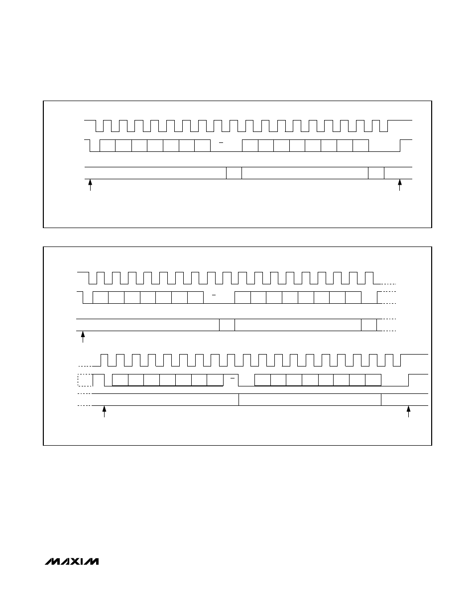
In read mode (R/W = 1), the MAX7472/MAX7473 write
the contents of the Status, Channel Selection, or
Frequency register to the bus. When the command
byte indicates a read operation of either the Status or
the Frequency register, the serial interface expects an
Sr condition to follow the command byte. After sending
an Sr, the master sends the MAX7472/MAX7473 slave
address byte followed by the R/W bit (set to 1 to indi-
cate a read). The slave device (MAX7472/MAX7473)
generates an ACK for the second address word and
immediately after the ACK clock pulse, the direction of
data flow reverses. The slave (MAX7472/MAX7473)
then transmits 1 byte of data containing the value of the
register that was selected in the command byte. Figure
8 shows a basic read sequence.
Note: To read the contents of the Status, Channel
Selection, or Frequency register, the master must first
write a command byte, requesting to read the Status,
Channel Selection, or Frequency register.
MAX7472/MAX7473
HDTV Anti-Aliasing Filters with Triple-Input Mux
______________________________________________________________________________________
13
SDA
SCL
1
0
0
1
0
A1
A0
R/W
C7
C6
C5
C4
C3
C2
C1
C0
ACK
ACK
OUT
IN
IN
OUT
IN TO MAX7472/MAX7473
COMMAND BITE IS FOR POWER-DOWN.
SDA
DIRECTION
START
0
0
0
0
0
0
0
0
STOP
Figure 7. Write Sequence for a Command Bite
R/W
SDA
SCL
1
0
0
1
0
A1
A0
R/W
C7
C6
C5
C4
C3
C2
C1
C0
ACK
ACK
ACK
OUT
IN
OUT
IN TO MAX7472/MAX7473
SDA (CONT)
SDA
DIRECTION
SDA
DIRECTION
SCL (CONT)
D7
1
D6
D5
D4
D3
D2
D1
ACK
OUT
D0
0
0
0
1
A1
A0
IN
IN
START
Sr
STOP
0
0
0
1
0
0
1/0
1
Figure 8. Basic Read Sequence