Hdtv anti-aliasing filters with triple-input mux – Rainbow Electronics MAX7473 User Manual
Page 14
MAX7472/MAX7473
Control/Status Register
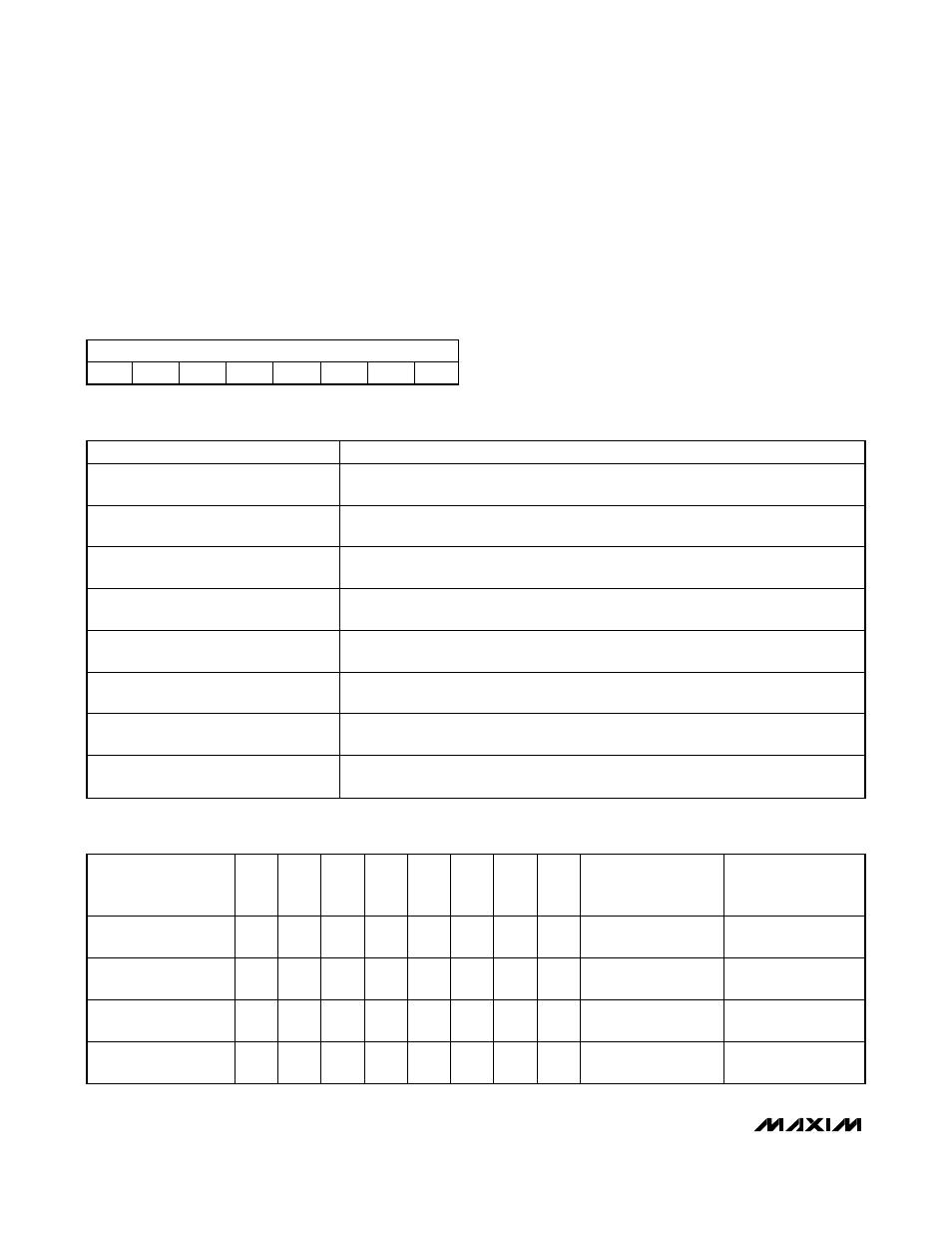
The MAX7472/MAX7473 store their status in an 8-bit
register that can be read back by the master. The indi-
vidual bits of the Control/Status register are summa-
rized in Tables 4 and 5. The power-on default value of
this register is 03h.
Frequency Register
The frequency response (-3dB passband edge) of the
MAX7472/MAX7473 can be continuously varied in 256
linear steps by changing the codes in the Frequency
register (Table 6). See the
Command Byte
(
Write Cycle)
section for a write sequence to update the Frequency
register.
HDTV Anti-Aliasing Filters with Triple-Input Mux
14
______________________________________________________________________________________
Table 4. Control/Status Register
Table 5. Control/Status Register Bit Description
CONTROL/STATUS REGISTER
S7
S6
S5
S4
S3
S2
S1
S0
BIT
DESCRIPTION
S7
0 = component input signal selected (default).
1 = composite input signal selected.
S6
0 = internal sync enabled (default).
1 = external sync enabled.
S5
0 = external sync: positive polarity (default).
1 = external sync: negative polarity.
S4
0 = normal operation mode (default).
1 = power-down mode.
S3
0 = filters enabled (default).
1 = bypass mode—no filtering.
S2
0 = clamp voltage for IN1 set to low (default).
1 = clamp voltage for IN1 set to high.
S1
0 = clamp voltage for IN2 set to low.
1 = clamp voltage for IN2 set to high (default).
S0
0 = clamp voltage for IN3 set to low.
1 = clamp voltage for IN3 set to high (default).
Table 6. Suggested Frequency Register Setting for Various Video-Signal Formats
VIDEO-SIGNAL
FORMAT
F7
F6
F5
F4
F3
F2
F1
F0
CODE NUMBER
APPROXIMATE
FREQUENCY
(-3dB) (MHz)
Standard-Definition
Interlaced
0
0
1
0
1
0
0
0
40
10
Standard-Definition
Progressive
0
1
0
1
1
0
1
0
90
15
High-Definition Low
Bandwidth
1
1
0
1
1
1
0
0
220
30
High-Definition High
Bandwidth
1
1
1
1
1
1
1
1
255
34 (default)