Electrical characteristics (continued) – Rainbow Electronics MAX5099 User Manual
Page 5
MAX5099
Dual, 2.2MHz, Automotive Synchronous Buck
Converter with 80V Load-Dump Protection
_______________________________________________________________________________________
5
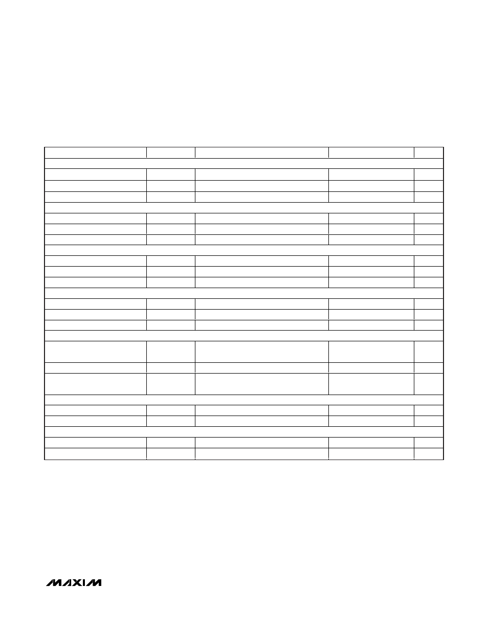
ELECTRICAL CHARACTERISTICS (continued)
(VDRV = V
L
, V+ = V
L
= IN_HIGH = 5.2V or V+ = IN_HIGH = 5.2V to 19V, EN_ = V
L
, SYNC = GND, I
VL
= 0mA, PGND = SGND,
C
BYPASS
= 0.22μF (low ESR), C
VL
= 4.7μF (ceramic), C
V+
= 1μF (low ESR), C
IN_HIGH
= 1μF (ceramic), R
IN_HIGH
= 3.9kΩ, R
OSC
= 10kΩ,
T
J
= -40°C to +125°C, unless otherwise noted.) (Note 2)
PARAMETER
SYMBOL
CONDITIONS
MIN
TYP
MAX
UNITS
INTERNAL DL_ DRIVERS
R
DS(ON)
DL_ Sink
R
ONDLN
I
SINK
= 200mA
1
Ω
R
DS(ON)
DL_ Source
R
ONDLP
I
SOURCE
= 200mA
1.8
Ω
Break-Before-Make Time
50
ns
FSEL_1
FSEL_1 Input High Threshold
V
IH
2
V
FSEL_1 Input Low Threshold
V
IL
0.8
V
FSEL_1 Input Leakage
I
FSEL_1_LEAK
2
μA
ON/OFF
ON/OFF Input High Threshold
V
IH
2
V
ON/OFF Input Low Threshold
V
IL
0.8
V
ON/OFF Input Leakage Current
I
ON/OFF_LEAK
V
ON/OFF
= 5V
0.35
2
μA
EN_ INPUTS
EN_ Input High Threshold
V
IH
EN_ rising
1.9
2.0
2.1
V
EN_ Input Hysteresis
V
EN_HYS
0.5
V
EN_ Input Leakage Current
I
EN_LEAK
-1
+1
μA
POWER-GOOD OUTPUT (PGOOD1, PGOOD2)
PGOOD_ Threshold
V
TPGOOD_
Falling
90
92.5
95
% V
FB_
PGOOD_ Output Voltage
V
PGOOD_
I
SINK
= 3mA
0.4
V
PGOOD_ Output Leakage
Current
I
LKPGOOD_
V+ = V
L
= V
IN_HIGH
= V
EN_
= 5.2V,
V
PGOOD_
= 23V, V
FB_
= 1V
2
μA
OUTPUT OVERVOLTAGE PROTECTION
FB_ OVP Threshold Rising
V
OVP_R
107
114
121
% V
FB
FB_ OVP Threshold Falling
V
OVP_F
112.5
% V
FB
THERMAL PROTECTION
Thermal Shutdown
T
SHDN
Rising
+165
°C
Thermal Hysteresis
T
HYST
20
°C
Note 2: 100% tested at T
A
= +25°C and T
A
= +125°C. Specifications at T
A
= -40°C are guaranteed by design and not production
tested.
Note 3: Operating supply range (V+) is guaranteed by V
L
line regulation test. Connect V+ to IN_HIGH and V
L
for 5V operation.
Note 4: Output current is limited by the power dissipation of the package; see the
Power Dissipation section in the Applications
Information section.