Rainbow Electronics MAXQ7670 User Manual
Page 35
MAXQ7670
Microcontroller with 10-Bit ADC,
PGA, 64KB Flash, and CAN Interface
______________________________________________________________________________________
35
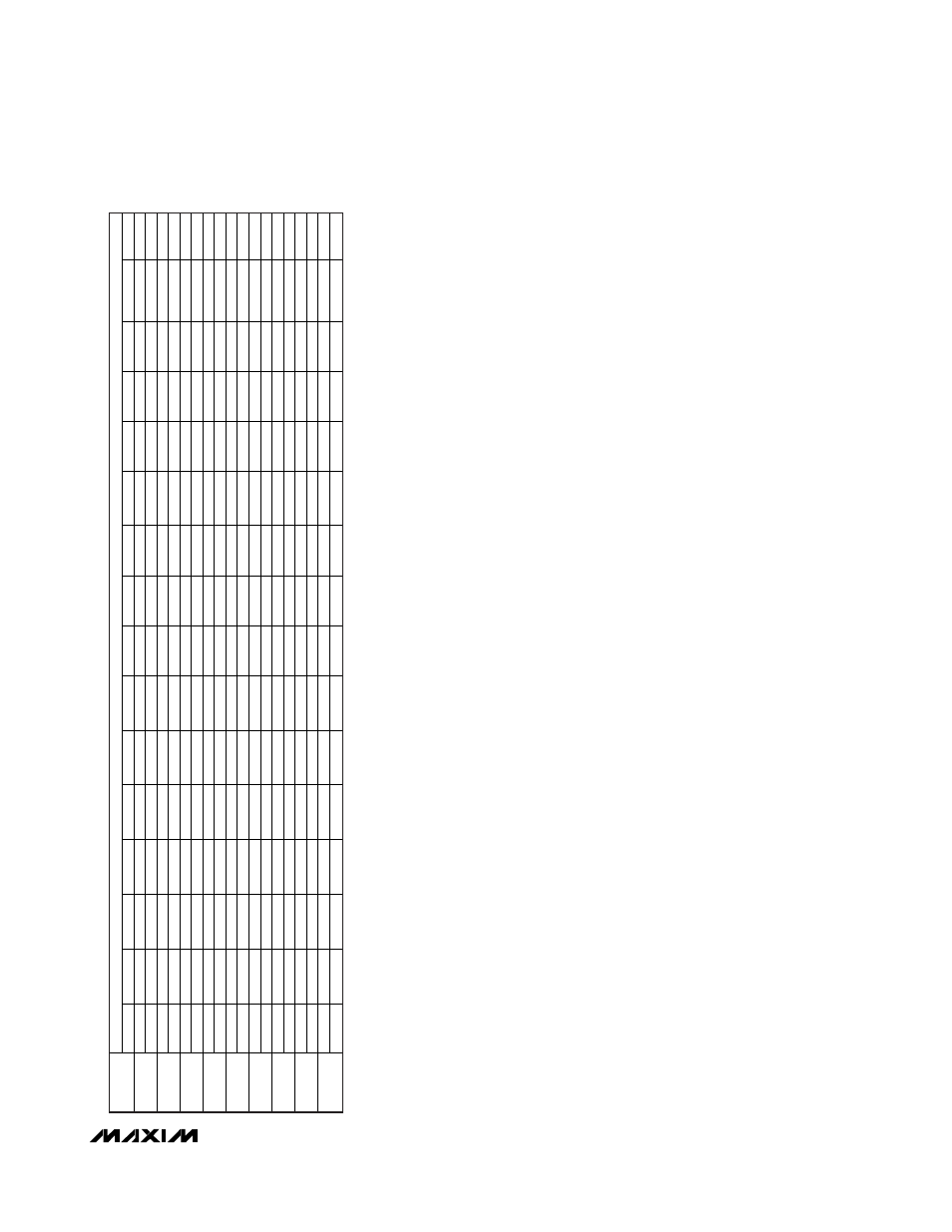
Bits indicated by “—“ are unused.
Bits indicated by “DB” have read/write access only in background or debug mode. These bits are cleared after a POR.
Bits indicated by “DW” are only written to in debug mode. These bits are cleared after a POR.
The OSCC register is cleared to 0002h after a POR and is not affected by other forms of reset.
REGISTER BIT
REGISTER
15
14
13
12
11
10
9
8
7
6
5
4
3
2
1
0
—
—
—
————
—
MSRDY
ETI
ERI
INTRQ
EXTRQ
MTRQ
ROW/
TIH
DTUP
C0M13C
0
0
0
0000
0
0
0
0
0
0
0
0
0
—
—
—
————
—
MSRDY
ETI
ERI
INTRQ
EXTRQ
MTRQ
ROW/
TIH
DTUP
C0M14C
0
0
0
0000
0
0
0
0
0
0
0
0
0
—
—
—
————
—
MSRDY
ETI
ERI
INTRQ
EXTRQ
MTRQ
ROW/
TIH
DTUP
C0M15C
0
0
0
0000
0
0
0
0
0
0
0
0
0
—
—
LRAPD
VIBE
VDBE
VDPE
VABE
—
—
—
PGG0
—
—
BIASE
—
ADCE
APE
0
0
1
0010
0
0
0
0
0
0
0
0
0
—
ADCMX3
ADCMX2
ADCMX1
ADCMX0
—
ADCBIP
—
—
ADCDUL
ADCRSEF
ADCASD
ADCBY
ADCS2
ADCS1
ADCS0
ACNT
—
0
0
0000
0
0
0
0
0
0
0
0
0
—
—
—
—
—
—
ADCD.9
ADCD.8
ADCD.7
ADCD.6
ADCD.5
ADCD.4
ADCD.3
ADCD.2
ADCD.1
ADCD.0
ADCD
0
0
0
0000
0
0
0
0
0
0
0
0
0
—
—
—
————
—
—
HFFIE
VIOBIE
DVBIE
AVBIE
—
ADCIE
—
AIE
0
0
0
0000
0
0
0
0
0
0
0
0
0
VIOLVL
DVLVL
AVLVL
—
XHFRY
—
—
—
—
HFFINT
VIOBI
DVBI
AVBI
—
ADCRY
—
ASR
0
0
0
0000
0
0
0
0
0
0
0
0
0
—
—
—
————
—
—
ADCCD1
ADCCD0
—
—
XTE
RCE
—
OSCC
0
0
0
0000
0
0
0
0
0
0
0
0
0
Table 5. Peripheral Register Bit Functions and Reset Values (continued)