System clock generator, Watchdog timer – Rainbow Electronics MAXQ7670 User Manual
Page 22
MAXQ7670
Microcontroller with 10-Bit ADC,
PGA, 64KB Flash, and CAN Interface
22
______________________________________________________________________________________
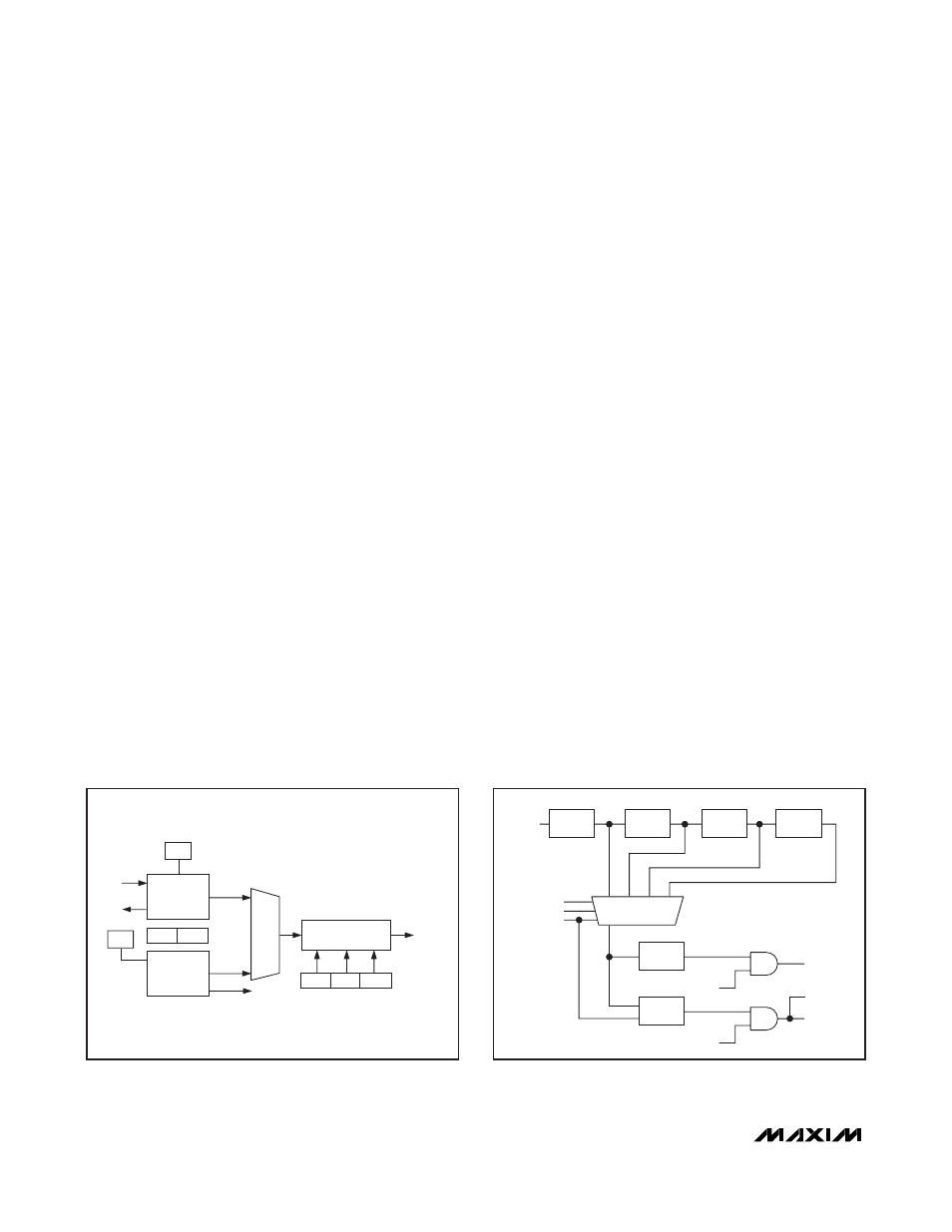
System Clock Generator
The MAXQ7670 oscillator module provides the master
clock generator that supplies the system clock for the
µC core and all of the peripheral modules. The high-fre-
quency oscillator operates with an 8MHz or 16MHz
crystal. Alternatively, use the integrated RC oscillator in
applications that do not require precise timing. The
MAXQ7670 executes most instructions in a single
SYSCLK period. The oscillator module contains all of
the primary clock generation circuitry. Figure 7 shows a
block diagram of the system clock module.
The MAXQ7670 contains the following features for gen-
erating its master clock signal timing source:
• Internal, fast-starting, 15MHz RC oscillator eliminates
external crystal
• Internal high-frequency oscillator that can drive an
external 8MHz or 16MHz crystal
• External high-frequency 0.166MHz to 16MHz clock input
• Power-up timer
• Power-saving management modes
• Fail-safe modes
Watchdog Timer
The primary function of the watchdog timer is to super-
vise software execution, watching for stalled or stuck
software. The watchdog timer performs a controlled
system restart when the µC fails to write to the watch-
dog timer register before a selectable timeout interval
expires. A watchdog timer typically has four objectives:
1) To detect if a system is operating normally
2) To detect an infinite loop in any of the tasks
3) To detect an arbitration deadlock involving two or
more tasks
4) To detect if some lower priority tasks are not getting
to run because of higher priority tasks
As illustrated in Figure 8, the internal RC oscillator
(CLK_RC) drives the watchdog timer through a series
of dividers. The programmable divider output deter-
mines the timeout interval. When enabled, the interrupt
flag WDIF sets. A system reset occurs after a time
delay (based on the divider ratio) unless an interrupt
service routine clears the watchdog interrupt.
The watchdog timer functions as the source of both the
watchdog interrupt and the watchdog reset. The inter-
rupt timeout has a default divide ratio of 2
12
of the
CLK_RC, with the watchdog reset set to timeout 2
9
clock cycles later. With the nominal RC oscillator value
of 15MHz, an interrupt timeout occurs every 0.273ms,
followed by a watchdog reset 34µs later. The watchdog
timer resets to the default divide ratio following any
reset event. Use the WD0 and WD1 bits in the WDCN
register to increase the watchdog interrupt period.
Changing the WD[1:0] bits before a watchdog interrupt
timeout occurs (i.e. before the watchdog reset counter
begins) resets the watchdog timer count. The watch-
dog reset timeout occurs 512 RC oscillator cycles after
the watchdog interrupt timeout. For more information on
the MAXQ7670 watchdog timer, refer to the
MAXQ7670
User’s Guide.
CD1
CD0
PMME
SYSCLK
MUX
CLK_RC
CLOCK
DIVIDE
HF
XTAL
OSC
RC
OSC
XIN
XOUT
XT
EXTHF
RCE
HFE
Figure 7. High-Frequency and RC Oscillator Functional
Diagram
EWDI
WD0
RWT
WD1
CLK_RC
(15MHz)
INTERRUPT
WTRF
RESET
WDIF
TIMEOUT
TIME
2
12
DIV 2
12
DIV 2
3
DIV 2
3
DIV 2
3
2
15
2
18
2
21
EWT
RESET
Figure 8. Watchdog Functional Diagram