Pin description (continued) – Rainbow Electronics MAXQ7670 User Manual
Page 15
MAXQ7670
Microcontroller with 10-Bit ADC,
PGA, 64KB Flash, and CAN Interface
______________________________________________________________________________________
15
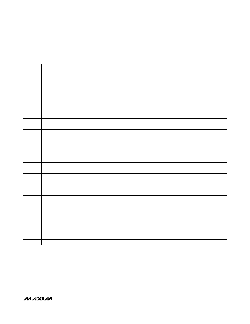
Pin Description (continued)
PIN
NAME
FUNCTION
23
SCLK
SPI Serial Clock. SCLK is the SPI interface serial clock I/O. In SPI master mode, SCLK is an output. While in
SPI slave mode, SCLK is an input.
24
MOSI
SPI Serial Data I/O. MOSI is the SPI interface serial data output in master mode or serial data input in slave
mode.
25
MISO
SPI Serial Data I/O. MISO is the SPI interface serial data input in master mode or serial data output in slave
mode.
26
REGEN2
Active-Low +2.5V Linear Regulator Enable Input. Connect REGEN2 to GNDIO to enable the +2.5V linear
regulator. Connect to DVDDIO to disable the +2.5V linear regulator.
27
TDO
JTAG Serial Test Data Output. TDO is the JTAG serial test, data output.
28
TMS
JTAG Test Mode Select. TMS is the JTAG test mode, select input.
29
TDI
JTAG Serial Test Data Input. TDI is the JTAG serial test, data input.
30
TCK
JTAG Serial Test Clock Input. TCK is the JTAG serial test, clock input.
31
P0.4/
ADCCNV
Port 0 Bit 4/ADC Start Conversion Control. P0.4 is a general-purpose digital I/O with interrupt/wake-up
capability. ADCCNV is a firmware-configurable, rising or falling edge, start/convert signal used to trigger
ADC conversions. The alternative function, ADCCNV, is selected using the register bits ACNT[2:0]. When
using ADCCNV as a trigger for ADC conversion, set P0.4/ADCCNV as an input using the PD0 register. This
action prevents any unintentional interference in the SARADC operation.
32
P0.5
Port 0 Bit 5. P0.5 is a general-purpose digital I/O with interrupt/wake-up capability.
33
RESET
Reset Input/Output. Active-low input/output with internal 55k
Ω pullup to DVDDIO. Drive low to reset the
MAXQ7670. The MAXQ20 µC core holds RESET low during POR and during DVDD brownout conditions.
34
DGND
Digital Ground
35
XOUT
High-Frequency Crystal Output. Connect an external crystal to XIN and XOUT for normal operation, or leave
unconnected if XIN is driven with an external clock source. Leave unconnected if an external clock source
is not used.
36
XIN
H i g h- Fr eq uency C r ystal Inp ut. C onnect an exter nal cr ystal or r esonator to X IN and X OU T for nor m al op er ati on,
or d r i ve X IN w i th an exter nal cl ock sour ce. Leave unconnected i f an exter nal cl ock sour ce i s not used .
37
DVDD
D i g i tal S up p l y V ol tag e. D V D D sup p l i es i nter nal d i g i tal cor e and fl ash m em or y. D V D D i s d i r ectl y connected to
the outp ut of the i nter nal + 2.5V l i near r eg ul ator . D i sab l e the i nter nal r eg ul ator ( thr oug h REG EN 2) to connect an
exter nal sup p l y. Byp ass D V D D to D GN D w i th a 0.1µF cap aci tor as cl ose as p ossi b l e to the d evi ce.
40
AVDD
Analog Supply Voltage. AVDD supplies PGA and ADC. AVDD is directly connected to the output of the
internal +3.3V linear regulator. Disable the internal regulator (via software) to connect an external supply.
Bypass AVDD to AGND with a 0.1µF capacitor as close as possible to the device.
—
EP
Exposed Pad. Connect EP to the ground plane.