Applications information, 5v regulator, Thermal protection – Rainbow Electronics MAX16800 User Manual
Page 6: Programming the led current, Input voltage considerations, Low-frequency pwm at the output
MAX16800
High-Voltage, 350mA, Adjustable Linear
High-Brightness LED (HB LED) Driver
6
_______________________________________________________________________________________
power series pass device (see the Functional
Diagram). The regulation point is factory set at (V
CS+
-
V
CS-
) = 204mV ±3.5%. The regulated current is user
defined by the value of R
SENSE
.
The MAX16800 is a current controller internally opti-
mized for driving the impedance range expected from
one or more HB LEDs.
+5V Regulator
The MAX16800 includes a fixed +5V output regulator
that delivers up to 4mA of load current for low-power
applications throughout the +6.5V to +40V input volt-
age range. Connect a 0.1µF compensation capacitor
from V5 to ground. Shorting V5 to ground disables the
thermal shutdown.
Thermal Protection
The MAX16800 enters a thermal-shutdown mode in the
event of overheating. This typically occurs in overload or
output short-circuit conditions. When the junction tem-
perature exceeds T
J
= +155°C (typ), the internal ther-
mal-protection circuitry turns off the series pass device.
The MAX16800 recovers from thermal-shutdown mode
once the junction temperature drops by 23°C (typ). The
part will therefore protect itself by thermally cycling in the
event of a short-circuit or overload condition.
Applications Information
Programming the LED Current
The MAX16800 uses a sense resistor across CS+ and
CS- to set the LED current. The differential sense ampli-
fier connected across R
SENSE
provides ground-loop
immunity and low-frequency noise rejection. The LED
current is given by the equation below:
I
LED
= V
SENSE
/ R
SENSE
Input Voltage Considerations
For proper operation, the minimum input voltage must
always be +1.2V (+1.5V for V
IN
<+12V) higher than the
worst-case sum of all the forward drops of all series-
connected LEDs to the output of the MAX16800. The
minimum operating voltage of the device is +6.5V. The
device will operate below +6.5V; however, output cur-
rent may not meet the full regulation specification (see
the Typical Operating Characteristics).
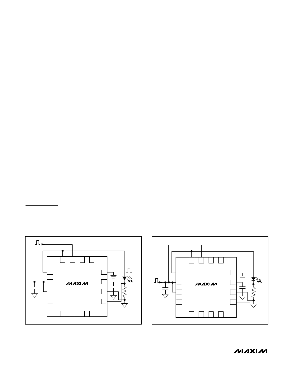
Low-Frequency PWM at the Output
The MAX16800 provides pulsed or chopped current
dimming. Generally, high-brightness LEDs are binned
to match at their full-rated current; however, LEDs from
the same bin exhibit poor matching at currents other
than full-rated current. To achieve uniformity, HB LED
manufacturers recommend PWM pulsing of the LED
current at their full-rated value. There are two methods
for producing a PWM output. One method is by pulsing
the enable input (EN) while having a constant voltage
at IN. The other method is to connect EN to IN and
pulse both EN and IN. Both methods generate a regu-
lated-amplitude PWM current (variable duty cycle) that
can provide control over the LED brightness (see
Figures 1 and 2).
3
4
2
1
10
9
11
12
5
6
IN
8
16
15
13
IN
C1
V
IN
N.C.
GND
V5
CS-
C2
D1
R
SENSE
CS+
MAX16800
7
N.C.
N.C.
N.C.
N.C.
OUT
EN
N.C.
N.C.
14
OUT
V
EN
I
LED
Figure 1. Pulse Application with V
IN
at a Constant Voltage
3
4
2
1
10
9
11
12
5
6
IN
8
16
15
13
IN
C1
V
IN
N.C.
GND
V5
CS-
C2
D1
R
SENSE
CS+
MAX16800
7
N.C.
N.C.
N.C.
N.C.
OUT
EN
N.C.
N.C.
14
OUT
I
LED
Figure 2. Pulse Application with EN Connected to V
IN