System settings, Operation modes, System clock – TC Electronic Impact Twin User Manual
Page 18
Operation Modes
You can select between four operation modes: “Normal”
and Safe Mode 1, 2 and 3. “Normal” is the default mode.
The various safe modes should only be selected if
you experience problems with clicks and pops caused
by DPC spikes. Use the DPC SPIKE checker tool as
described to isolate such problems.
ASIO Buffer Size*
The buffer size can be set from 64 to 8192 samples.
You should only increase the buffer size if you
experience problems such as clicks or pops in the sound
that are not caused by DPC spikes.
The buffer size range depends on the selected operation
mode.
Normal Mode: 64 – 8192
Safe Mode 1: 224 – 8192
Safe Mode 2: 224 – 8192
Safe Mode 3: 224 – 8192
You can manually set the buffer size to any number you
wish within the given range. However, the number should
be dividable with 8.
The minimum buffer range will always apply and will
automatically be selected when you change between the
modes.
Example #1
When you switch from “Normal” mode with the buffer size
set to 64 to “Safe Mode 2”, the buffer is automatically
changed to 224.
Example #2
When you switch from “Normal” mode with the buffer size
set to 256 to “Safe Mode 2”, the buffer is not changed –
256 is above the minimum value (224) for this range.
Example #3
When you switch from “Safe Mode 2” with the buffer size
SYSTEM SETTINGS
SYSTEM SETTINGS
33
32
B: Drop-outs caused by DPC spikes
If you increase your buffer size but still experience audio
dropouts, DPC spikes may be the cause of the problem.
DPC spikes typically occur if one or more hardware
components in your system (e.g. network adapters,
wireless network adapters or optical drives) have poor
drivers.
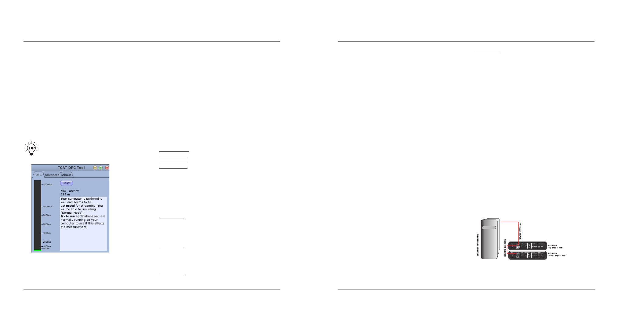
First of all, you should check your system using the DPC
SPIKE CHECKER TOOL that is installed in the same
folder as the TC Near Control Panel. Spikes will show in
the meter, and – based on an analysis over time – the
tool will suggest an operation mode (Safe Mode 1, 2 or
3). Select the suggested Operation Mode in the control
panel and you should be all set to go.
Once you have isolated problems resulting from
DPC spikes, you can try lowering your buffer
size again for least latency.
Advanced Tab (for system testing purposes)
On the “Advanced” tab, you can generate spikes.
Activate a spike inducer and set how often spikes should
occur.
set to 224 to “Normal” mode, the buffer is not changed
as the minimum setting for “Normal” mode is 64. You
can, however enter a different value manually.
* ASIO buffer size is relevant for PCs running Windows
operating systems only. On Mac computers, the buffer size
is set within the audio application. For instance, in Ableton
Live go to “Preferences” / “Audio Drivers” to set the buffer
size.
Please note that clicks and pops in the sound may also
result from clock problems. These should be resolved first.
System Clock
In a studio setup where there is more than one digital
device, and where the digital devices are connected
using digital connections, it is important that all devices
run at the exact same sample rate – in other words, they
all have to refer to the same system clock.
Only one device can provide the system clock, and with
the parameters in the “System Clock” section you specify
which device provides the system clock.
Clock Master
The audio interface that provides the system clock
is called the clock master. With the Clock Master
parameter, you select which audio interface should be
the clock master. Of course, this is only relevant if you
have more than one audio interface in your setup. When
connected to a computer, it is always the audio interface
that is audio clock master – the computer itself cannot be
clock master.
Sync Source
With the Sync Source parameter you specify which part
of the clock master will provide the system clock. The
options are either to choose the device itself (INTERNAL)
or to choose one of the device’s digital inputs.
Options are:
TOS S/PDIF
ADAT INTERNAL
The most used setting will be INTERNAL. Using this
setting, the internal DICE II clock provides the system
clock to the other devices in the studio setup. In most
cases, this is the best option.
The other options are only relevant if you attach external
digital devices to your audio interface using the S/PDIF
or the ADAT/TOS Lightpipe input connectors.
If you have attached an external audio device to one of
the digital inputs, please consider whether this external
device should provide the system clock. If so, select the
digital input that you have used for that device.
Please note that due to the JetPLL jitter reduction,
Impact Twin is able to reject jitter coming from external
digital devices.
Example 1 – Impact Twin as Clock Master:
Setting Clock Master and Sync Source
The setup consists of two Impact Twin units connected
via FireWire, a computer and an ADAT interface. We
assigned the nicknames “My Impact Twin” and “Peter’s
Impact Twin” (nicknames are set on the “About” page).
The intention here is to sync the entire setup to the
ADAT interface.
• Set “Clock Master” on the System Settings page to