Vision control panel layout, Vision control panel – Grain Systems PNEG-1459 User Manual
Page 9
9
PNEG-1459 L Series Operators
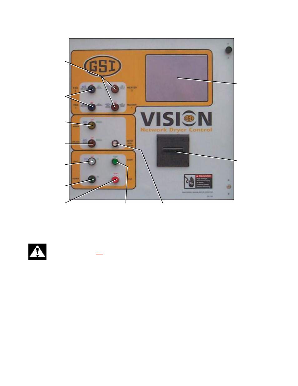
Touch Screen
Fan Switches
Load Auger Switch
Operator Light
Switch
Control Power Switch
Heater Switches
Unload Auger
Switch
Stop Switch
Start Switch
Meter Roll Speed
Moisture Manager
Printer (Optional)
Vision Control Panel Layout
CONTROL POWER SWITCH
The control power to energize the Vision Control System is turned on or off with this switch.
Note: This switch does not disconnect the power that is present at the breakers, contactors, transformer(s),
fuses or other electrical components found in the upper and lower control boxes. Turn the Main Disconnect
Handle to the OFF position prior to servicing any of the installed components.
FAN SWITCH
Each fan is turned on or off with this switch. The on position operates the fan continuously during staged batch and continuous
flow modes. The auto position operates the fan in staged batch during the dry and cool cycle but the fan will not operate during
the unload cycle. The switch will light up whenever the air pressure switch is sensing air pressure and the dryer is full of grain.
Note: The bottom fan on your dryer is always Fan 1.
HEATER SWITCH
Each burner is turned on or off with this switch. The auto position operates the burner in staged batch during the dry cycle only.
The on position will operate the burner only when the fan is running. The switch will light up only when the flame sensor
detects the flame.
Note: The bottom burner on your dryer is always Burner 1.
VISION CONTROL PANEL