Grain Systems Unload Augers PNEG-1722 User Manual
Page 18
4. Assembly
18
PNEG-1722 Series II Sweep Protected Cord Slip Ring Sump
20. Make sure that the lower shroud assembly and the drilled conduit exit hole in the sump wall hole
are aligned. Bolt the cross brace assembly to the sump using eight (8) 1/2" x 1-3/4" hex bolts,
flat washers, lock washers and hex nuts.
21. Slide the lower shroud assembly into position against the sump wall. Tack weld the lower shroud
assembly to the sump wall.
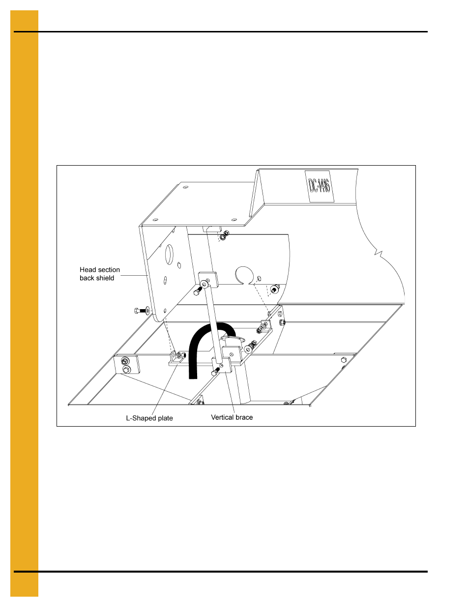
22. Without damaging the slip ring stranded wires, connect the L-shaped pivot plate to the head section
back shield using two (2) 1/2" x 1-3/4" hex bolts, flat washers, lock washers and hex nuts.
23. Without damaging the slip ring stranded wires, fasten the vertical brace rod to the head section
back shield and L-shaped pivot plate using two (2) 1/2" x 2" hex bolts, lock washers and hex nuts.
Figure 4F
24. Feed the nine (9) stranded wires from the slip ring through the horizontal tube assembly. Take care
to ensure that none of the wires becomes stripped or damaged in this process.
25. Feed the horizontal tube assembly and nine (9) stranded wires from the slip ring through the hole
in the head section back shield.
26. Attach the horizontal pivot tube and vertical pivot tube together using five (5) 1/4" x 1" hex bolts and
serrated flange nuts. It is critical that the two (2) flanges are seated and create a proper seal so that
contaminants do not enter the space around the stranded wires.