Grain Systems Unload Augers PNEG-1722 User Manual
Page 15
4. Assembly
PNEG-1722 Series II Sweep Protected Cord Slip Ring Sump
15
3. Once the assembly is aligned properly, attach the cross brace to the sump with four (4) 1/2" x 1-3/4"
hex bolts and nuts. Do not tighten these at this point.
4. Using the lower shroud assembly, mark the center lines of the plate onto the sump wall. These
marks will be used to create the conduit exit hole through the sump wall.
5. Once the marks have been double checked on the wall, unbolt the cross assembly from the sump
and remove the slip ring shield from the cross brace assembly.
6. Drill up to a 2" hole at the marked location on the sump wall. Remove any burrs created in the drilling
process from the conduit exit hole in the sump wall.
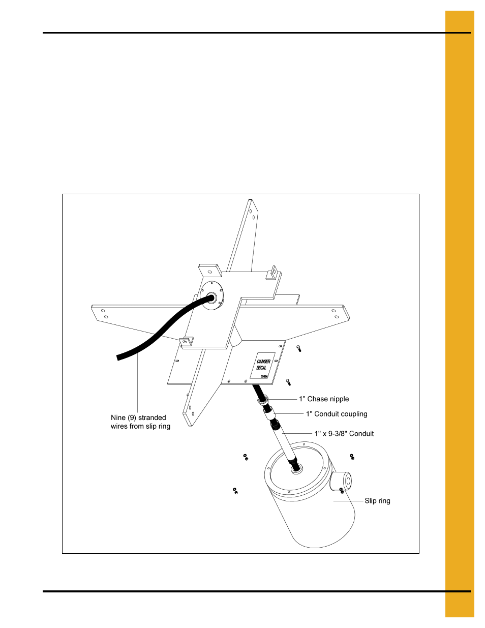
7. Assemble the 1" x 9-3/8" conduit to the 1" chase nipple using one 1" conduit coupling.
8. Feed the nine (9) stranded wires from the slip ring through the conduit assembly and fasten it to the
slip ring.
Figure 4C
- Bin Accessories PNEG-1883 (26 pages)
- Bin Accessories PNEG-104 (2 pages)
- Bin Accessories PNEG-1859 (90 pages)
- Tanks PNEG-4075 (168 pages)
- Bin Accessories PNEG-1789 (7 pages)
- Special Roofs PNEG-1845 (28 pages)
- Unload Augers PNEG-1550 (22 pages)
- Bucket Elevtors, Conveyors, Series II Sweeps PNEG-1842 (114 pages)
- Tanks PNEG-1784 (5 pages)
- Bin Accessories PNEG-1336D (34 pages)
- Bucket Elevtors, Conveyors, Series II Sweeps PNEG-1618 (10 pages)
- Tanks PNEG-4072G (162 pages)
- Unload Augers PNEG-1556 (58 pages)
- Bin Accessories PNEG-268 (2 pages)
- Bin Flooring PNEG-1830 (44 pages)
- Tanks PNEG-603 (56 pages)
- Bin Flooring PNEG-1835 (48 pages)
- Bin Flooring PNEG-1816 (42 pages)
- Bin Accessories PNEG-1870 (28 pages)
- Bin Accessories PNEG-1088 (30 pages)
- Tanks PNEG-1880 (30 pages)
- Tanks PNEG-4054G (168 pages)
- Unload Augers PNEG-1583 (28 pages)
- Bin Accessories PNEG-318 (180 pages)
- Bucket Elevtors, Conveyors, Series II Sweeps PNEG-970 (36 pages)
- Bin Flooring PNEG-219 (32 pages)
- Tanks PNEG-083 (28 pages)
- Bin Flooring PNEG-1826 (42 pages)
- Bin Accessories PNEG-1802 (50 pages)
- Unload Augers PNEG-1521 (64 pages)
- Tanks PNEG-4090A (166 pages)
- Bin Accessories PNEG-1933 (2 pages)
- Bin Accessories PNEG-1496 (2 pages)
- Bucket Elevtors, Conveyors, Series II Sweeps PNEG-1902 (7 pages)
- Bin Accessories PNEG-1177 (16 pages)
- Bucket Elevtors, Conveyors, Series II Sweeps PNEG-1204 (59 pages)
- Bin Accessories PNEG-130 (2 pages)
- Bin Accessories PNEG-1451 (102 pages)
- Tanks PNEG-1095 (76 pages)
- Bin Accessories PNEG-1868 (26 pages)
- Bin Accessories PNEG-1840 (32 pages)
- Unload Augers PNEG-790 (18 pages)
- Tanks PNEG-1461 (124 pages)
- Bin Accessories PNEG-1884 (26 pages)
- Bin Accessories PNEG-1852 (26 pages)