Grain Systems Unload Augers PNEG-1722 User Manual
Page 16
4. Assembly
16
PNEG-1722 Series II Sweep Protected Cord Slip Ring Sump
9. Feed the nine (9) stranded wires from the slip ring through the vertical pivot tube rubber grommet
and bolt the slip ring to the cross brace assembly using four (4) 1/4" x 1" hex bolts, lock washers
and hex nuts. It is important that the rubber grommet remains stationary and intact. Failure to do
so can result in severed wires during operation.
Electrical controls and wiring should be installed by a qualified electrician. The motor disconnect
switches and conductor cables should comply with the National Electrical Code and any local
codes which apply. Reset and motor starting stations should be located so that the operator can
see that all personnel are clear of the equipment.
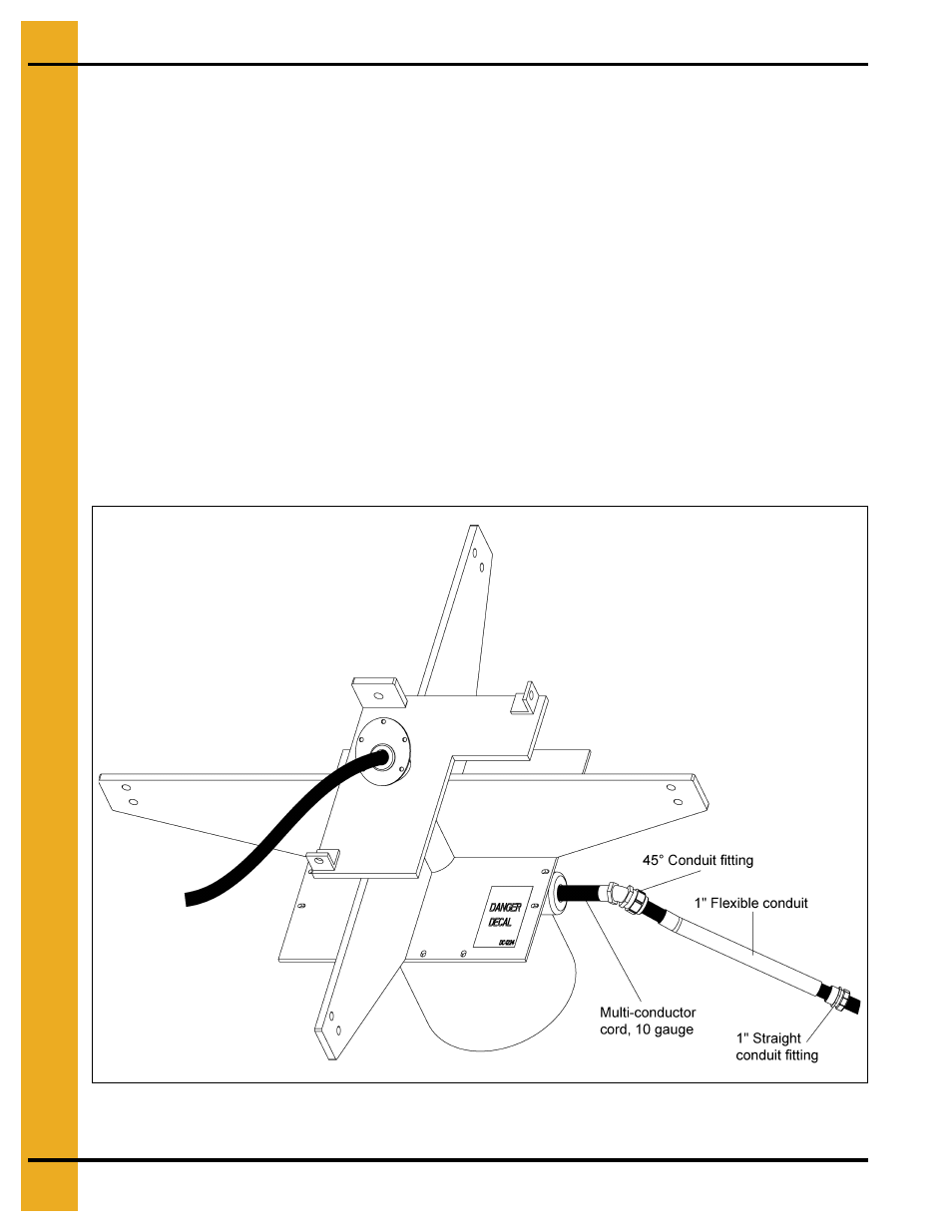
NOTE: The liquid-tight flex conduit may need to be trimmed to length.
10. Attach the 1" liquid-tight flex conduit coupling to one end of the 1" x 16" liquid-tight flex conduit.
11. Attach the 1" x 45° liquid-tight flex conduit coupling to the other end of the 1" x 16" liquid-tight
flex conduit.
12. Remove the protective housing from the slip ring.
13. Feed the multi-conductor cord through the conduit assembly and the 1" conduit hub on the slip ring.
14. Attach the 1" x 45° liquid-tight flex conduit coupling to the 1" conduit hub on the slip ring. Be sure
to turn the conduit assembly down.
Figure 4D