Banks Power Ford Trucks: (Diesel ’94 - 97 7.3L Power Stroke) Power Systems- PowerPack, Stinger-Plus & Stinger '94-98 4" Exhaust User Manual
Page 8
1.
Reinstall the dipstick tube, dipstick
and cooler line if removed. Be sure
to connect the electrical ground
between the cylinder head and
dipstick mount for the transmission.
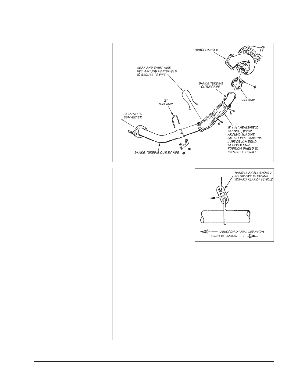
2.
secure the heatshield blanket
provided to the Banks turbine outlet
pipe with the wire ties provided, as
shown in Figure 4. loosely clamp the
upper portion of the turbine outlet
pipe to the exhaust backpressure
control valve on the turbocharger.
Slide the 3-inch clamp over the end
of the lower turbine outlet pipe.
reinstall the catalytic converter in
its original position and install the
lower portion of the turbine outlet
pipe between the upper pipe and
catalytic converter from underneath
the vehicle. adjust the position of
the turbine outlet pipe to allow the
maximum amount of clearance
between the pipe and the firewall.
Tighten the 3-inch clamp at the pipe
joint under the vehicle and the V-
band clamp at the turbine outlet.
3.
Place a 3-
1
⁄
2
” clamp on the inlet
of the supplied rear intermediate
& install the pipe onto the catalytic
converter outlet. Be sure the
notch and catalytic converter pin
are properly aligned. install the
intermediate pipe hanger in the
vehicle’s rubber hanger. lightly snug
the 3-
1
⁄
2
” clamp onto the front of
the intermediate pipe / catalytic
converter outlet.
4.
Place a 4” clamp on the inlet of
the Monster muffler. (note, ccLB
models will use a single pin hanger
clamp on the front of the muffler.
install the monster muffler inlet (note
the inlet labeling of the muffler) onto
the intermediate pipe outlet. orient
the monster logo such that is visible
from the passenger side and parallel
with the frame rail. align the clamp
onto the muffler inlet.
5.
install the dual hanger pin rear
muffler hanger clamp onto the
monster muffler outlet. install the
hanger pin the vehicles rubber
hanger. route the tailpipe over the
rear axle housing and into the muffler
outlet. loosely snug the 4” hanger
clamp onto the muffler outlet.
6.
install the 5” monster tailpipe tip
on the exhaust. Keep the wrapping
on until installation is complete. the
tip should be rotated so the clamp
nut and drain hole are pointing down.
align the end of the tip with the body
line of the truck.
7.
with everything positioned
properly, begin to tighten the clamps
starting with the ones closest to the
front and working your way back.
Torque the exhaust clamps evenly to
35 ft-lbs. Make sure that each slip is
fully inserted (+/-
1
⁄
4
inch) and that
all mount hangers are in the forward
position (see Figure 5).
8.
remove the protective covering
from the tailpipe tip. Caution: the
protective covering may ignite and
burn if not removed prior to running
the engine.
9.
If the monster exhaust is the
only banks product being installed,
re-connect negative battery
cable(s). start the engine and
listen for exhaust leaks. Tighten
the exhaust clamps as necessary.
Whenever possible, tack-welding
slip connections to prevent
disengagement is recommended.
10.
To reconnect the exhaust
backpressure control valve, hold the
cover on the end of the rod back
and have someone start the engine.
When the rod extends after a few
seconds, push it up onto the valve
linkage and allow the cover to snap
back into position. WARNING! Stay
clear of moving parts such as the
engine cooling fan and belts. Do
not drive the vehicle until the
remainder of the installation is
complete. Any airborne objects
entering the turbocharger may
cause damage.
11.
While the engine is running,
check for oil leaks around the base
of the turbocharger center section or
the pedestal mount. repair any leaks
before continuing.
NOTE: The most likely cause of
an oil leak in this installation is a
pinched O-ring at the base of the
turbocharger.
-EnD, SEcTIon 3-
Section 3
MONSTER ExHAUST INSTALLATION
Figure 5
Figure 4
8
96493 v.4.0