Banks Power Ford Trucks: (Diesel ’94 - 97 7.3L Power Stroke) Power Systems- PowerPack, Stinger-Plus & Stinger '94-98 4" Exhaust User Manual
Page 16
GAUGE PANEL
1.
if the gauges are being installed
into an existing gauge panel, this
step may be skipped. if gauges and
a gauge panel are being installed,
choose a location where the gauges
can be easily viewed by the driver.
this will typically be to the right of
the accelerator pedal, under the
lower edge of the dash panel. mount
the gauge panel with the machine
screws, washers, and nuts provided.
NOTE: Molded instrument panels for
top of dash mounting are available
from Gale Banks Engineering.
DYNAFACT PYROMETER
2.
install the Dynafact
®
pyrometer
probe (supplied in the pyrometer kit)
in the
1
⁄
4
-inch nPt bung located at
the top of the turbine outlet pipe.
Use anti-seize compound on the
threads. Connect the lead-wire to the
sensor with the supplied screws. the
wires are different lengths to prevent
cross connecting. make sure that the
screws are tight. slip the heat shrink
tubing provided over the wire ends.
3.
supply moderate heat to the heat
shrink tubing to seal the connections.
a heat-gun or lighter works well.
4.
when passing through the firewall
either make a hole in a factory
grommet or drill a hole and use a
new grommet. if a hole needs to
be drilled, drill a
5
⁄
16
-inch hole and
debur it on both sides, so that the
wiring or tubing does not get cut
as it passes through the hole. for
added protection, wrap the wiring
with several layers of electrical tape
in the area where it passes through
the hole. When drilling, check the
backside to make sure that there
are no components blocking the
backside of the hole that would be
damaged by drilling.
5.
route the pyrometer lead-wire
up and across the top of the firewall
then down and through the hole
in the firewall. Inside the vehicle,
route the wire to the gauge location.
if routing the lead-wire under the
carpet, avoid placing it where the
driver’s feet will rest on the wire. tie
the wire to existing wire looms and
hoses with the cable ties provided.
6.
Position the gauge through the
console or gauge panel. slip the
plastic U-clamp, provided with the
pyrometer, over the studs on the rear
of the gauge and tighten the nuts,
provided.
imPortant: remove the bare
shorting wire from between the
gauge terminals before connecting
the lead-wire to the pyrometer.
attach the spade connectors to
the back of the gauge. Connect the
yellow wire to the (+) terminal and
the red wire to the (-) terminal. if the
lead-wires are accidentally reversed,
the gauge will read backwards.
7.
Pull any excess wire through
the firewall, coil it and secure it up
under the dash, out of the way. Do
not shorten the lead-wire. Note: If
it is necessary to replace one of the
terminal ends, use a crimp tool only.
Do not solder to the wires.
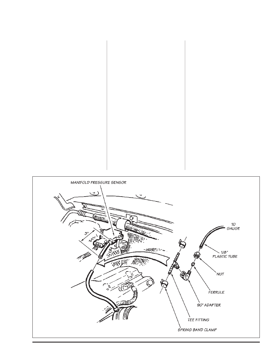
Section 5
DYNAFACT INSTRUMENTATION INSTTALLATION
Figure 15
16
96493 v.4.0