Banks Power Ford Trucks: (Diesel ’94 - 97 7.3L Power Stroke) Power Systems- PowerPack, Stinger-Plus & Stinger '94-98 4" Exhaust User Manual
Page 18
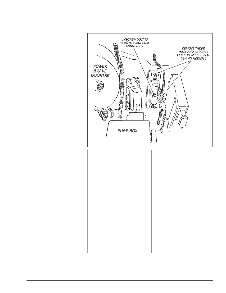
1.
Be certain battery ground cables
have been disconnected. locate
the engine control unit (eCu) in a
recess in the firewall on the engine
side, between the steering column
and the left front fender. all that will
be visible is an elongated electrical
connector and wire loom, surrounded
by a retainer plate attached with two
nuts. see Figure 16.
2.
remove the bolt attaching the
electrical connector to the EcU,
unplug the connector, and swing it
out of the way.
3.
remove the two nuts and
retaining plate from against the
firewall. Pull the eCu out of the
firewall toward the front of the
vehicle. it may be necessary to
remove the rearmost bolts attaching
the flexible inner fenderwell to the
body to provide clearance to remove
the eCu.
4.
note the code printed on the
plastic cap on the back of the
eCu. this code should compare
to the code printed on the Banks
ottoMind™ box label. Pry the plastic
cap from the rear of the eCu using
a small screwdriver, exposing the
printed circuit board edge connector
inside. retain the plastic cap. the
connector will be coated with grease
and a clear silicone type coating
which must be completely removed
before installing the Banks ottomind
engine calibration module.
5.
Clean Both sides of the
connector. First, clean the white
grease off with a tissue. next, scrape
the clear silicone type coating from
the connector fingers with the
abrasive square provided. it is very
important to clean both sides of
the board in order to have a good
connection between the eCu and the
Banks ottomind module. it is only
necessary to clean the connector
fingers. Be careful not to damage any
circuit traces on the board further
inside the eCu.
6.
orient the module so that its
edges line up with the edges of the
EcU. If the edges do not line up,
or it looks as if the eCu will not fit
back into the hole in the firewall, the
module is rotated 180 degrees off.
Place the ottomind module over the
connector, and press firmly to seat
the connection. Do not forCe the
ottoMind onto the connector, as
damage may result to either the eCu
or the module. if the module does
not install with firm pressure, check
the orientation and try again. Place a
piece of duct tape over the module,
fastening it firmly to the eCu. see
Figure 17.
7.
Before returning the eCu to the
recess in the firewall, it is a good
idea to reconnect the wire harness
and the batteries and start the
vehicle. the vehicle may not start if
the coating on the eCu connector is
not completely removed or if there
is a mismatch of codes. a quick
indication of module connections that
are not cleaned properly is that the
“wait to start” indicator will fail to
light and the “Check engine” warning
indicator will stay lit after the key
is switched on. if the engine fails to
start, re-clean the EcU connector,
reinstall the module and try again.
After the engine has started, shut it
off, disconnect the batteries and the
EcU wire harness, and complete the
installation.
8.
reinstall the eCu in the firewall.
reinstall the retaining plate against
the firewall. reattach the wire
harness to the eCu. reinstall the
inner wheel well bolts, if removed.
reconnect the batteries.
9.
start the engine and allow it
to warm up. Drive the vehicle,
listening for any exhaust leaks or
rattles. adjust and tighten clamps
or reposition the piping if required.
when positioning of piping is
finalized, it is a good practice to
place tack welds at any slip joints
in the exhaust system to prevent
slippage. NOTE: The exhaust may
smoke slightly after initial startup.
This is normal and will go away
shortly as the grease used in the
bending process burns off the inside
of the piping.
-EnD, SEcTIon 6-
Section 6
BANKS OTTOMIND ENGINE CALIBRATION MODULE INSTALLATION
Figure 16
18
96493 v.4.0