Banks Power Chevy_GMC Trucks: Duramax LLY-LBZ (Diesel ’06 - 07 6.6L) Power Systems- PowerPack & Stinger Systems w EconoMind (LLY & LBZ) '06-07 (iQ) Compatible with Optional Banks iQ User Manual
Page 8
8
96816 v.3.0
ExHauST SYSTEM INSTaLLaTION
Use the Bill of Materials Chart and
Figure 1.0 or 1.1 to reference
component nomenclature and
location. Use caution when working
in the engine compartment. Make
sure the engine has been OFF for
several hours and cool.
1.
Disconnect the ground of the
battery (if there is more than one
battery, disconnect both).
2.
Raise the vehicle and support it
with properly weight rated safety
stands, ramps or a commercial hoist.
Follow the manufacturer’s safety
precautions. Take care to balance
the vehicle to prevent it from slipping
or falling. When using ramps, be
sure the front wheels are centered
squarely on the topsides; place the
transmission in park; set the parking
brake and place blocks behind the
rear wheels.
CauTION: DO NOT WORk uNDER
aNY VEHICLE SuPPORTED ONLY
BY a JaCk. SEVERE INJuRY MaY
RESuLT.
CauTION: The following step
involves cutting a stainless steel
tube. Safety glasses should
be worn during any cutting
operation and care should be
taken to avoid injury due to sharp
edges and burrs.
3.
Removal of the factory exhaust
can be simplified by cutting the
factory exhaust pipe behind the
muffler. This will allow the tailpipe to
be removed as a separate piece.
4.
Remove the clamp located on
catalytic converter outlet
5.
Remove the factory tailpipe
from the vehicle by disengaging the
exhaust system hanger pins from
the rubber insulators using a large
screw-driver or pry bar.
NOte: Lubricating the rubber hangers
with WD-40 or similar lubricant will
ease removal of the hanger pins.
6.
Remove the factory muffler
from the vehicle by disengaging
the hanger pins from the rubber
insulators using a large screwdriver
or pry bar.
7.
Install a 3.5” saddle clamp onto
the catalytic converter outlet.
8.
Insert the intermediate pipe inlet
onto the flanged intermediate pipe
outlet. Install the intermediate pipe
hanger pin(s) into the vehicle rubber
insulators.
NOte: Once the pipe has been
completely engaged in the slip
joint, it should be marked with a
marker, scribe or tape for reference
when tightening clamps later in the
installation. each slip joint in the
system should be marked in this
fashion. When the exhaust system is
being adjusted to align the hangers,
the slip joints can be adjusted so that
the reference mark is no more than
1
⁄
4
” away from its original position.
Step 16 thru 23 applies only to
single tailpipe systems.
Skip to Step 24 if installing Banks
Split-Dual Monster exhaust System.
Single Tailpipe System (Step 9
thru 16)
9.
Slide one (1) of the supplied
4-inch exhaust clamps over the
Banks intermediate pipe.
NOte: On extended cab long-bed
and crew-cab long-bed vehicle, the
clamp that is used between the
intermediate pipe and muffler is a
combination hanger/clamp. When
this hanger clamp is installed the
hanger pin should be inserted into
the factory rubber hanger and the
clamp should be rotated until the
hanger pin is parallel with the frame-
mounted pin before being torqued.
10.
Install the muffler onto the end
of the intermediate pipe outlet. Be
sure that the inlet side of the muffler
(see markings on muffler body)
is facing toward the front of the
vehicle. Orient the muffler such that
the “Banks Monster” logo is facing
towards the frame and is level with
the ground. Verify that the muffler
and intermediate pipe are completely
engaged.
11.
Slide one (1) of the supplied
4” exhaust clamps onto the Banks
Monster muffler outlet.
12.
Install the tailpipe into the outlet
of the muffler. Be sure that the two
pipes are completely engaged. Insert
the front and rear tailpipe hanger
pins into the factory rubber hangers.
Rotate the tailpipe until the hanger
pins are parallel with the frame
mounted pin.
NOte: Minimum distance between
exhaust tip and body a one (1) inch.
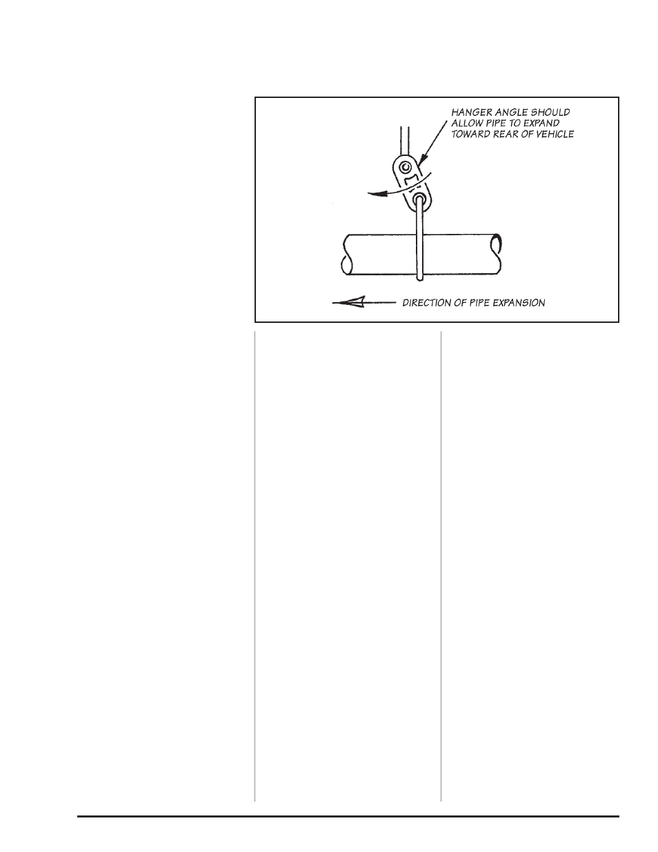
13.
Adjust each of the pipes to
ensure that all of the hanger pins
are parallel with the frame-mounted
pins and that the rubber hangers are
all positioned slightly forward (See
Figure 1.2). The amount of forward
angle on the rubber hangers should
increase the farther downstream the
hanger is positioned. This allows the
hangers to be properly positioned
once the exhaust system reaches
operating temperature.
14.
Tighten the head pipe V-band
clamp to 12 ft-lbs (if previously
loosened).
15.
Install the exhaust clamp
at each of the three (3) joints.
Figure 1.3 illustrates the proper
location of an exhaust clamp on a
tubing joint. Torque the nuts on each
of the exhaust clamps to 35 ft-lb.
Figure 1.2