Step 1 - open the touch panel, Step 2 – disconnect the connector cable, Step 3 - choose a wiring method – Velleman LEDC13 User Manual
Page 4: Step 4 - attach the controller on the wall
LEDC13
V. 01 – 28/03/2013
4
©Velleman nv
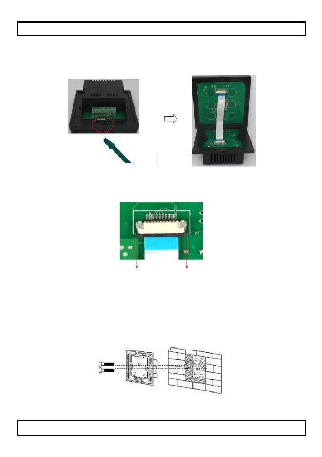
Step 1 - Open the touch panel
As shown, gently open the touch panel (for example with a small
screwdriver).
Step 2 – Disconnect the connector cable
Open the connector and gently remove the connector cable.
Step 3 - Choose a wiring method
Connect the wires according to the mode you will use (see section
Wiring below).
Step 4 - Attach the controller on the wall
Attach and screw the controller to the wall as shown in the picture.
The distance between the screws is 60mm.
See also other documents in the category Velleman Lighting:
- VDPLTC2 (18 pages)
- VDPL1003CW (34 pages)
- VDLPS36BL3 (14 pages)
- VDPL300HD (31 pages)
- VDLP56LBS (16 pages)
- VDPL300DD (23 pages)
- VDPSP0x (17 pages)
- VDLLTC series (16 pages)
- VDL25ST (13 pages)
- XMCL13 (16 pages)
- VTLLAMP1W (10 pages)
- VDP1500ST (22 pages)
- VTLAMP5W (18 pages)
- VDPLW2401 (21 pages)
- VDPLP710RGBWB (34 pages)
- VDP750ST (22 pages)
- VDPL1210MHRGBW (58 pages)
- VDPDP136 (23 pages)
- VDPC146 (58 pages)
- NLROD3x (13 pages)
- VDLP575C (18 pages)
- VDLLT series (16 pages)
- VDL50CM3 (22 pages)
- VTLAMP8 (19 pages)
- VLP20B (18 pages)
- VDLLUF (23 pages)
- VDLL300TS (16 pages)
- VDPL300MF4 (32 pages)
- OFKx (5 pages)
- VDL360RL2 (18 pages)
- VDL50CM2 (230V version) (16 pages)
- VDL660RL (15 pages)
- VDPL1803MHRGB (57 pages)
- VTLLAMP5W (18 pages)
- VDPSP151 (10 pages)
- VDLLMS1 (23 pages)
- ZLLS1 (16 pages)
- VDPLT2 (16 pages)
- VDPLOW3601 (22 pages)
- VDPL303BS (30 pages)
- VDLP56LB (12 pages)
- VDLL300MF (12 pages)
- VDP575MHW16FL (39 pages)
- NLRODx (13 pages)
- VDPLW1601 (24 pages)