Velleman KSR4 User Manual
Page 2
KSR4 VELLEMAN
2
4. Assembly
a) PCB Assembly
Start the assembly by mounting the resistors. The names of all components have been printed on the PCB:
Part ID
Description
Colour Code
Quantity
R18
100Ω
brown/black/brown/gold
1
R11/12/13/14
10Ω
brown/black/black/gold
4
R3/4
16Ω
brown/blue/black/gold
2
R1
39Ω
orange/white/black/gold
1
R5/7/8/9/10
1K
brown/black/red/gold
5
R15
10K
brown/black/orange/gold
1
R2/6/16/17
22K
red/red/orange/gold
4
Mount the zener diode, the capacitors, the transistors and the oscillator next:
Part ID
Description
Quant.
ZD1
Zener diode 3.9V
1
C2/3
ceramic capacitor 30
2
C1
ceramic capacitor 103
1
C4
ceramic capacitor 104
1
C5
ceramic capacitor 224
1
EC1
electrolytic capacitor 100uf
1
Q5/6/7/8
transistor 8550
4
Q2
transistor 9013
1
Q1/3/4/9/10/11/12
transistor 8050
7
Q13/14/15/16
transistor C945
4
XTAL
oscillator 4MHz
1
Mount the IC socket, the battery connector, the slide switch, the buzzer and the pins.
Part ID
Description
Quant.
IC1
IC socket (fig.1 #12)
1
BAT.
battery connector (fig.1 #13)
1
SW.
slide switch (fig.1 #17)
1
BZ1
buzzer (fig.1 #6)
1
M1 (+/-)
M2 (+/-)
pins (fig.1 #16)
4
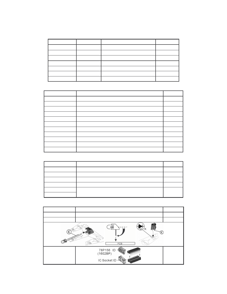
Mount the LED, the IR LEDs and the IC:
Part ID
Description
Quantity
LED1
LED 5mm (red)
1
LED2/3/4
IR LED 5mm (clear) + LED holder
3 + 3
REMARK:
IC1
1
Fig. 3