128 sal-rpm, Vishay bccomponents, 125 °c equivalent series resistance (esr) – C&H Technology 128 SAL-RPM User Manual
Page 7
128 SAL-RPM
Vishay BCcomponents
Aluminum Capacitors Solid Al,
Radial Pearl Miniature
www.vishay.com
For technical questions, contact:
Document Number: 28354
158
Revision: 31-Aug-09
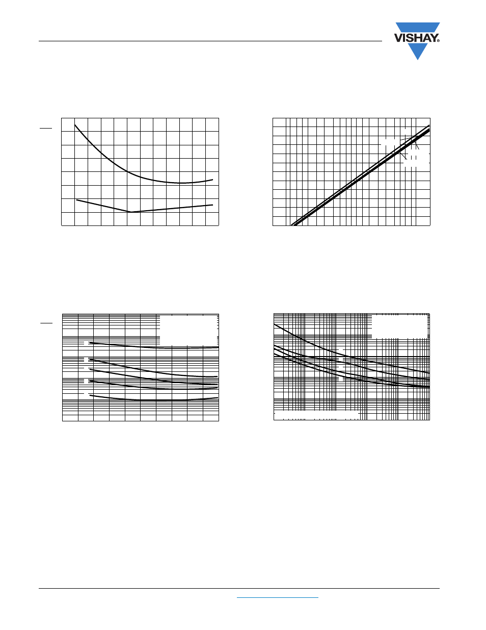
DISSIPATION FACTOR (tan
δ)
TYPICAL tan
δ CHANGE AFTER
ENDURANCE TEST AT T
amb
= 125 °C
EQUIVALENT SERIES RESISTANCE (ESR)
T
amb
(°C)
Fig.10 Typical multiplier of dissipation factor and standard deviation
as functions of ambient temperature
- 80 - 40 0 40 80 120 160
2.0
1.5
1.0
0.5
0
tan
δ
tan
δ
0
0.05
0
standard
de
v
iation
σ
σ
Tan
δ
0
= dissipation factor at Tamb = 25 °C and 100 Hz
Fig.11 tan
δ change of capacitance as a function of cumulative
frequency after endurance test
0.01 0.1 0.5 1 2 5 10 20 30 40 50 60 70 80 90 95 98 99 99.5 99.9 99.99
cumulative frequency (%)
tan
δ (
%
of initial re
qu
irements)
2000 h
5000 h
10 000 h
init.
120
100
80
60
40
20
0
T
amb
(°C)
Fig.12 Typical multiplier of ESR at 100 Hz as a function of
ambient temperature
10
4
10
3
10
2
10
1
10
-1
ESR
ESR
0
- 100 - 50 0 50 100 150
1
2
3
4
5
Curve 1: 0.22 µF, 40 V
Curve 2: 1.5 µF, 40 V
Curve 3: 3.3 µF, 25 V
Curve 4: 10 µF, 6.3 V
Curve 5: 22 µF, 10 V
10
6
10
5
10
4
10
3
10
2
f (Hz) 10
7
Fig.13 Typical ESR at 25 °C as a function of frequency
10
3
10
2
10
1
10
-1
10
-2
ESR
(Ω)
Curve 1: 0.22 µF, 40 V
Curve 2: 1.5 µF, 40 V
Curve 3: 2.2 µF, 16 V
Curve 4: 10 µF, 6.3 V
1
2
3
4
Case H x W x T = 10 x 7 x 3.5 mm