Thermal characteristics, Mechanical characteristics – C&H Technology CM1500HC-66R User Manual
Page 5
MITSUBISHI HVIGBT MODULES
CM1500HC-66R
HIGH POWER SWITCHING USE
4
th
-Version HVIGBT (High Voltage Insulated Gate Bipolar Transistor) Modules
INSULATED TYPE
HVIGBT (High Voltage Insulated Gate Bipolar Transistor) MODULES
HVM-1054-C 4 of 9
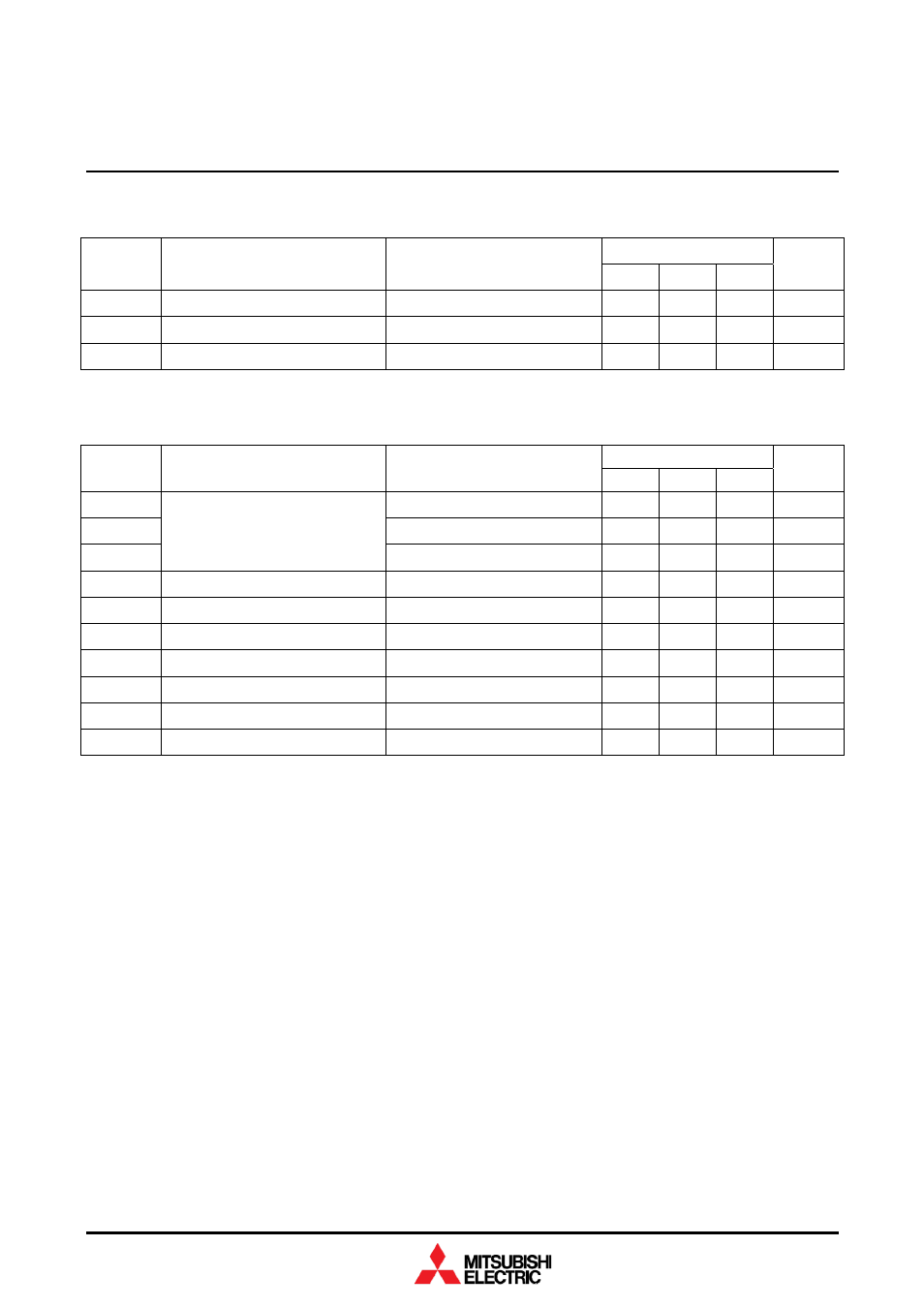
THERMAL CHARACTERISTICS
Limits
Symbol Item
Conditions
Min Typ Max
Unit
R
th(j-c)Q
Thermal resistance
Junction to Case, IGBT part
—
—
8.0
K/kW
R
th(j-c)R
Thermal resistance
Junction to Case, FWDi part
—
—
15.0
K/kW
R
th(c-f)
Contact
thermal
resistance
Case to Fin,
λ
grease
= 1W/m·K, D
(c-f)
= 100 µm
— 6.0 — K/kW
MECHANICAL CHARACTERISTICS
Limits
Symbol Item
Conditions
Min Typ Max
Unit
M
t
M8: Main terminals screw
7.0
—
22.0
N·m
M
s
M6: Mounting screw
3.0
—
6.0
N·m
M
t
Mounting torque
M4: Auxiliary terminals screw
1.0
—
3.0
N·m
m Mass
—
1.2
—
kg
CTI
Comparative tracking index
600
—
—
—
d
a
Clearance
19.5
—
—
mm
d
s
Creepage
distance
32.0
—
—
mm
L
P CE
Parasitic stray inductance
—
11.0
—
nH
R
CC’+EE’
Internal lead resistance
T
c
= 25°C
—
0.12
—
mΩ
r
g
Internal
gate
resistor
T
c
= 25°C
—
1.5
—
Ω
Note 1.
Pulse width and repetition rate should be such that junction temperature (T
j
) does not exceed T
opmax
rating (150°C).
Note 2.
The symbols represent characteristics of the anti-parallel, emitter to collector free-wheel diode (FWDi).
Note 3.
Junction temperature (T
j
) should not exceed T
jmax
rating (150°C).
Note 4.
Pulse width and repetition rate should be such as to cause negligible temperature rise.
Note 5.
E
on(10%)
/ E
off(10%)
/ E
rec(10%)
are the integral of 0.1V
CE
x 0.1I
C
x dt.
Note 6.
The integration range of E
on
/ E
off
/ E
rec
according to IEC 60747.