Vishay high power products, Full-bridge" igbt mtp (warp speed igbt), 50 a, Dt fig. 14 - typical stored charge vs. di – C&H Technology 25MT060WFAPbF User Manual
Page 6
Document Number: 94539
For technical questions, contact: [email protected]
www.vishay.com
Revision: 30-May-08
5
25MT060WFAPbF
"Full-Bridge" IGBT MTP
(Warp Speed IGBT), 50 A
Vishay High Power Products
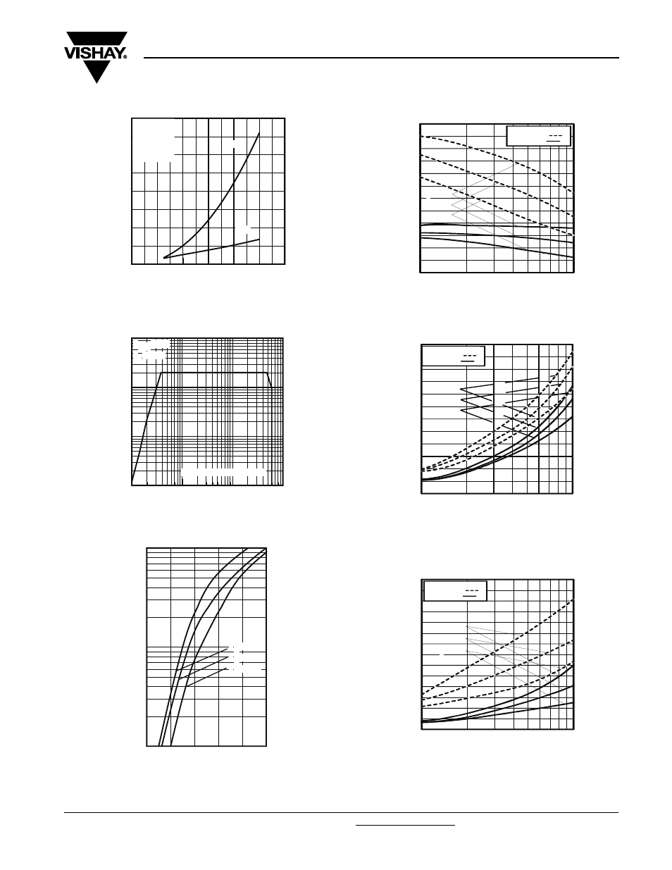
Fig. 9 - Typical Switching Losses vs.
Collector to Emitter Current
Fig. 10 - Turn-Off SOA
Fig. 11 - Maximum Forward Voltage Drop vs.
Instantaneous Forward Current
Fig. 12 - Typical Reverse Recovery Time vs. dI
F
/dt
Fig. 13 - Typical Reverse Recovery Current vs. dI
F
/dt
Fig. 14 - Typical Stored Charge vs. dI
F
/dt
0
10
20
30
40
50
60
IC, Collector Current (A)
0.0
0.5
1.0
1.5
2.0
S
w
it
c
h
in
g
L
o
s
s
e
s
(m
J
)
EOFF
EON
RG = 5.0Ω
TJ = 25°C
VGE = 15V
VCC = 480V
1
10
100
1000
VCE, Collector-to-Emitter Voltage (V)
1
10
100
1000
I C
,
C
o
lle
c
to
r-
to
-E
m
it
te
r
C
u
rr
e
n
t
(A
)
VGE = 20V
TJ = 125°
SAFE OPERATING AREA
0.4
0.8
1.2
1.6
2.0
2.4
Forward Voltage Drop - V F ( V )
1
10
100
In
s
ta
n
ta
n
e
o
u
s
F
o
rw
a
rd
C
u
rr
e
n
t
-
I
F
(
A
)
TJ = 150°C
TJ = 125°C
TJ = 25°C
20
40
60
80
100
120
140
0
0
0
1
0
0
1
f
di /dt - (A/μs)
I = 50A
I = 25A
I = 10A
F
F
F
V = 200V
T = 125°C
T = 25°C
R
J
J
trr-
(nC)
0
5
10
15
20
25
30
0
0
0
1
0
0
1
f
di /dt - (A/μs)
A
I = 50A
I = 25A
I = 10A
V = 200V
T = 125°C
T = 25°C
R
J
J
F
F
F
Irr-
(
A)
0
200
400
600
800
1000
1200
1400
0
0
0
1
0
0
1
f
di /dt - (A/μs)
I = 50A
I = 25A
I = 10A
V = 200V
T = 125°C
T = 25°C
R
J
J
F
F
F
Qrr-
(nC)