Vishay high power products, Full-bridge" igbt mtp (warp speed igbt), 50 a, Thermal - mechanical specifications – C&H Technology 25MT060WFAPbF User Manual
Page 4
Document Number: 94539
For technical questions, contact: [email protected]
www.vishay.com
Revision: 30-May-08
3
25MT060WFAPbF
"Full-Bridge" IGBT MTP
(Warp Speed IGBT), 50 A
Vishay High Power Products
Note
(1)
Standard version only i.e. without optional thermistor
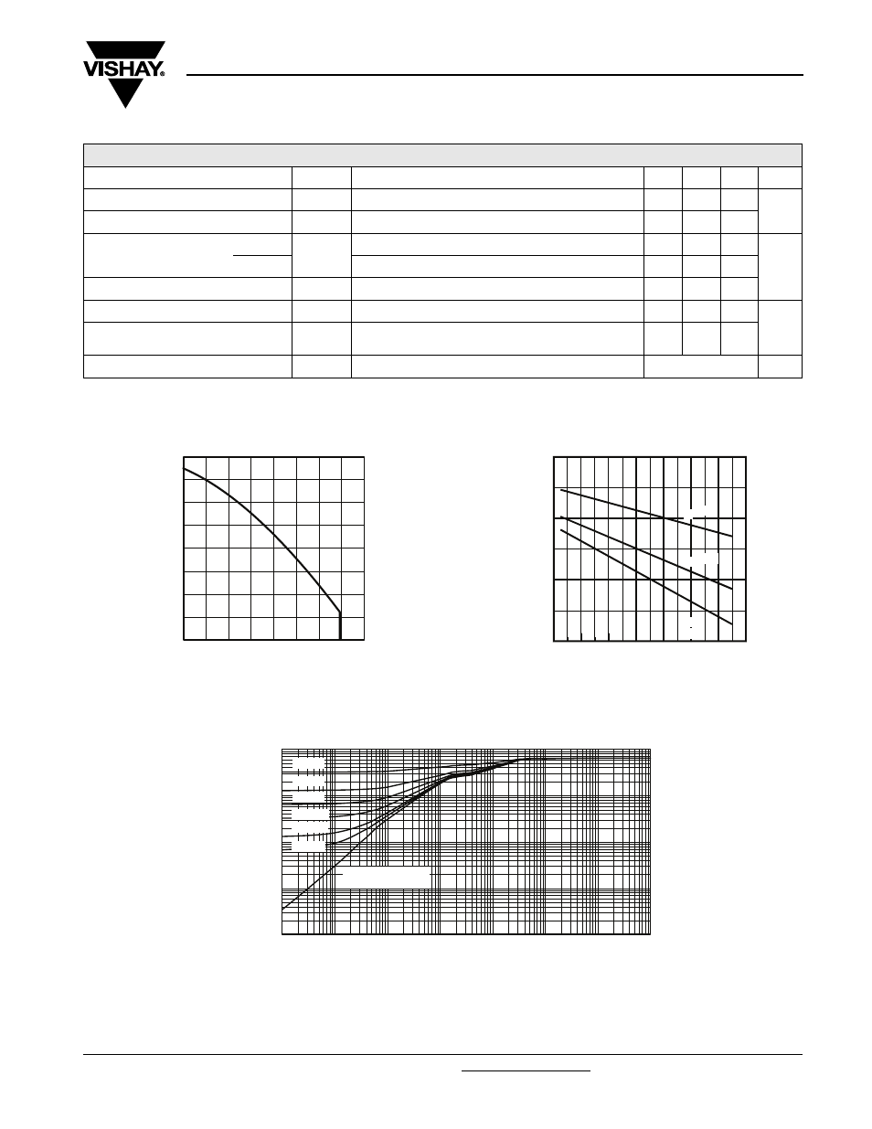
Fig. 1 - Maximum Collector Current vs.
Case Temperature
Fig. 2 - Typical Collector to Emitter Voltage vs.
Junction Temperature
Fig. 3 - Maximum Transient Thermal Impedance,
Junction to Case (IGBT)
THERMAL - MECHANICAL SPECIFICATIONS
PARAMETER
SYMBOL
TEST CONDITIONS
MIN.
TYP.
MAX. UNITS
Operating junction temperature range
T
J
- 40
-
150
°C
Storage temperature range
T
Stg
- 40
-
125
Junction to case
IGBT
R
thJC
-
-
0.64
°C/W
Diode
-
-
0.9
Case to sink per module
R
thCS
Heatsink compound thermal conductivity = 1 W/mK
-
0.06
-
Clearance
(1)
Externel shortest distance in air between two terminals
5.5
-
-
mm
Creepage
(1)
Shortest distance along external surface of the
insulating material between 2 terminals
8
-
-
Weight
66
g
T
C
Case Temperature (°C)
I
C
Maximum DC Collector Current (A)
0
20
40
60
80
100
120
140
160
0
10
20
30
40
50
60
70
80
20
40
60
80
100
120
140
160
TJ , Junction Temperature (°C)
1.25
1.75
2.25
2.75
V
C
E
,
C
o
lle
c
to
r-
to
E
m
it
te
r
V
o
lt
a
g
e
(V
)
IC = 50A
IC = 25A
IC =
12.5A
t
1
, Rectangular Pulse Duration (sec)
Thermal Response (Z
thJC
)
0.0001
0.001
0.01
0.1
1
0.000001
0.00001
0.0001
0.001
0.01
0.1
1
10
Single Pulse
(Thermal Response)
D = 0.5
D = 0.2
D = 0.1
D = 0.05
D = 0.02
D =0.01