Cpv363m4kpbf, Vishay semiconductors – C&H Technology CPV363M4KPbF User Manual
Page 7
CPV363M4KPbF
www.vishay.com
Vishay Semiconductors
Revision: 11-Jun-13
6
Document Number: 94485
For technical questions within your region:
,
,
THIS DOCUMENT IS SUBJECT TO CHANGE WITHOUT NOTICE. THE PRODUCTS DESCRIBED HEREIN AND THIS DOCUMENT
ARE SUBJECT TO SPECIFIC DISCLAIMERS, SET FORTH AT
www.vishay.com/doc?91000
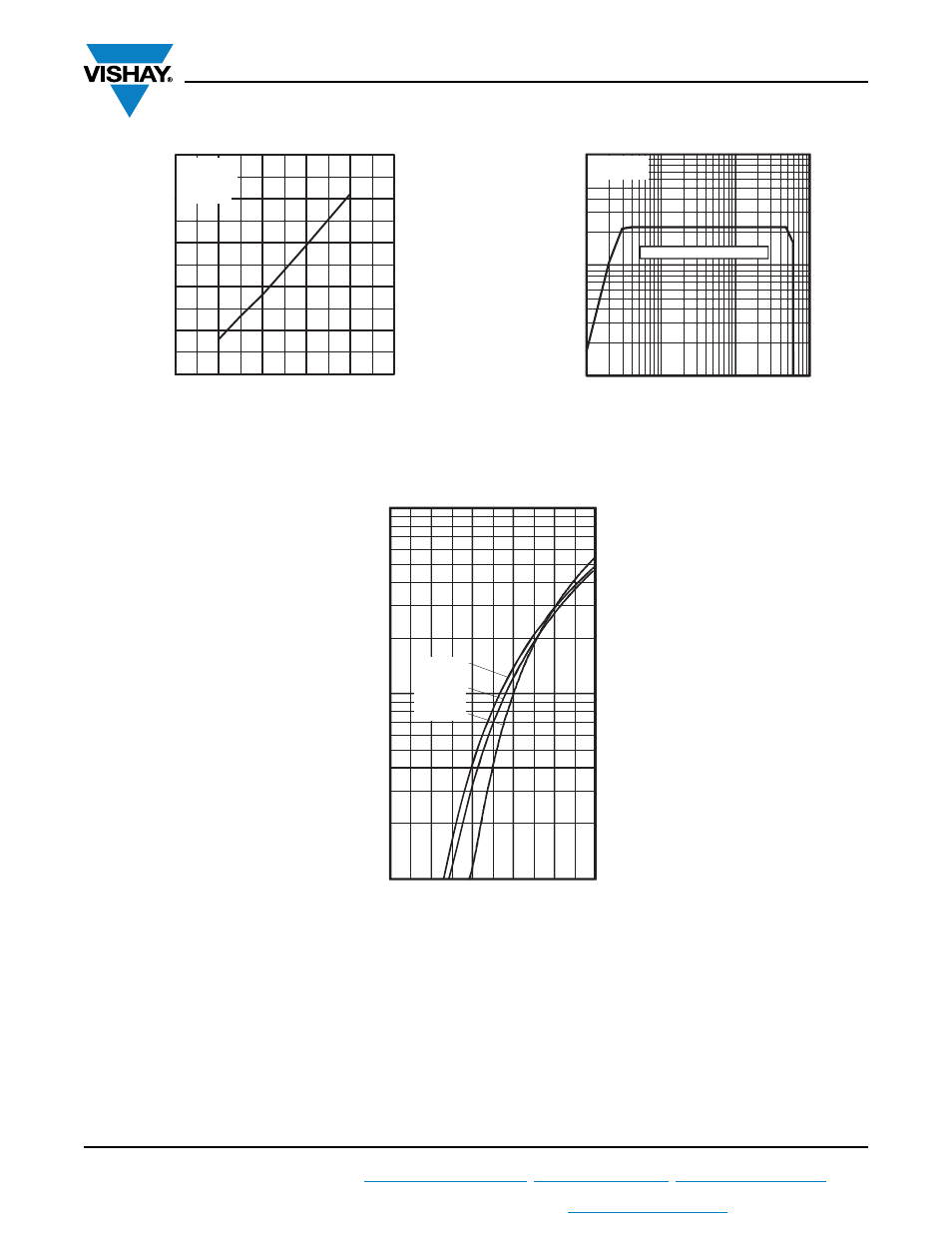
Fig. 11 - Typical Switching Losses vs.
Collector to Emitter Current
Fig. 12 - Turn-Off SOA
Fig. 13 - Maximum Forward Voltage Drop vs.
Instantaneous Forward Current
0
3
6
9
12
15
0.0
0.3
0.6
0.9
1.2
1.5
I , Collector-to-emitter Current (A)
To
ta
l Sw
it
c
h
in
g
L
o
s
s
e
s
(
m
J
)
C
R = 23
T = 150 C
V = 0V
V = 15V
G
J
CC
GE
°
Ω
480V
1
10
100
1
10
100
1000
C
CE
I
, C
o
llector
-to-E
m
itter
C
u
rr
ent (A
)
SAFE OPERATING AREA
V = 20V
T = 125°C
GE
J
V , Collector-to-Emitter Voltage (V)
A
1
10
100
0.4
0.8
1.2
1.6
2.0
2.4
FM
F
In
s
tant
a
n
eous
For
w
a
rd
C
u
rr
en
t
- I
(
A
)
Forward Voltage Drop - V (V)
T = 150°C
T = 125°C
T = 25°C
J
J
J
- TDK4_ _3302 (5 pages)
- CM75TL-12NF (5 pages)
- PM600HSA120 (5 pages)
- GLI......A (4 pages)
- PM600DVA060 (5 pages)
- VSKDS408-060 (10 pages)
- G200 (5 pages)
- VS30ASR..N Series (2 pages)
- LPS1100 (6 pages)
- PM50CL1B120 (6 pages)
- CPS (3 pages)
- PM200DSA060 (7 pages)
- RM400HA-34S (5 pages)
- VS-GB100TH120U (8 pages)
- PP300B120 (8 pages)
- PP400B060 (8 pages)
- PM100RLA060 (7 pages)
- PM25RL1A120 (8 pages)
- VS210DG..HCB Series (3 pages)
- RTO20 (5 pages)
- PM50B4LB060 (7 pages)
- VS-GT100DA120U (11 pages)
- PM200RLA060 (7 pages)
- ST380CHPbF Series (8 pages)
- RM1200DB-66S (11 pages)
- GB70NA60UF (6 pages)
- VS255SG..HCB Series (3 pages)
- EMF050J60U (18 pages)
- HFA30TA60CSPbF (6 pages)
- PM50CLB120 (5 pages)
- MBR10.. Series (7 pages)
- VS-GB300LH120N (7 pages)
- LTO100 (5 pages)
- ST303CLPbF Series (9 pages)
- PM100CVA060 (7 pages)
- ST230CPbF Series (8 pages)
- QR_1220T30 (5 pages)
- VS230LM06CS02CB (3 pages)
- ST303CPbF Series (9 pages)
- TDK4_ _3002 (5 pages)
- HFA240NJ40CPbF (8 pages)
- CT220802 (5 pages)
- VS-UFL130FA60 (8 pages)
- GB05XP120KTPbF (11 pages)
- VS-GT75NP120N (7 pages)