Vishay high power products, Thermal - mechanical characteristics – C&H Technology GB200TS60NPbF User Manual
Page 4
Document Number: 94503
For technical questions, contact: [email protected]
www.vishay.com
Revision: 07-May-08
3
GB200TS60NPbF
INT-A-PAK "Half-Bridge"
(Ultrafast Speed IGBT), 209 A
Vishay High Power Products
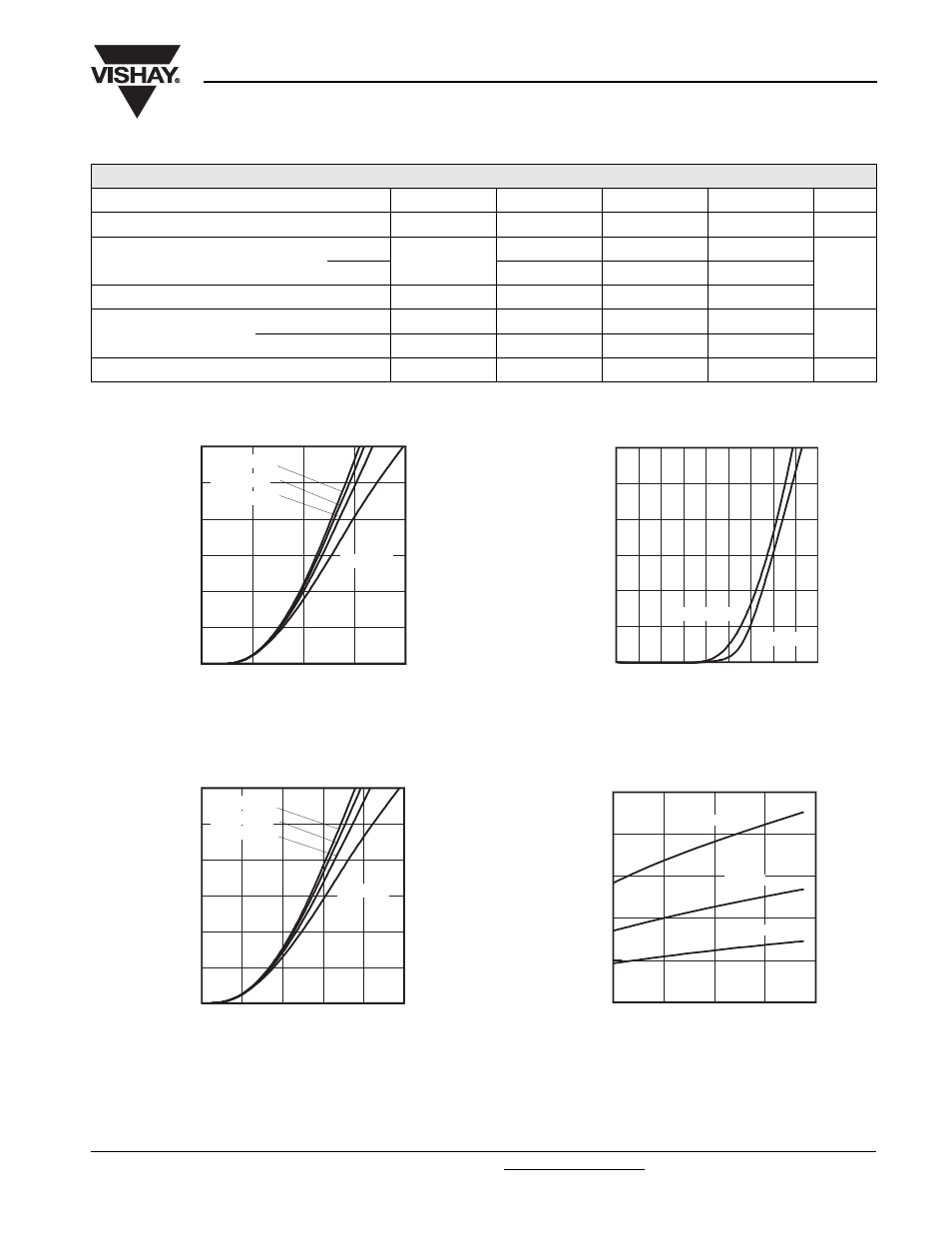
Fig. 1 - Typical IGBT Output Characteristics
T
J
= 25 °C, t
p
= 500 µs
Fig. 2 - Typical IGBT Output Characteristics
T
J
= 125 °C, t
p
= 500 µs
Fig. 3 - Typical Transfer Characteristics
V
CE
= 20 V, t
p
= 500 µs
Fig. 4 - Typical Collector to Emitter Voltage vs.
Junction Temperature
THERMAL - MECHANICAL CHARACTERISTICS
PARAMETER SYMBOL
MIN.
TYP.
MAX.
UNITS
Operating junction and storage temperature range
T
J
, T
Stg
- 40
-
150
°C
Junction to case per leg
IGBT
R
thJC
-
0.13
0.16
°C/W
Diode
-
0.19
0.32
Case to sink per module
R
thCS
-
0.1
-
Mounting torque
case to heatsink
-
-
4
Nm
case to terminal 1, 2, 3
-
-
3
Weight
-
185
-
g
I
cE
(A)
V
CE
(V)
0
1
2
3
4
0
50
100
150
200
250
300
Vge = 9V
Vge = 12V
Vge = 15V
Vge = 18V
I
cE
(A)
0
1
2
3
4
5
0
50
100
150
200
250
300
Vge = 9V
Vge = 18V
Vge = 15V
Vge = 12V
V
CE
(V)
I
cE
(A)
V
GE
(V)
0
1
2
3
4
5
6
7
8
9
0
50
100
150
200
250
300
Tj = 25°C
Tj = 125°C
0
40
80
120
160
1
1.5
2
2.5
3
3.5
Ic = 50A
Ic = 100A
Ic = 200A
T
J
, Junction Temperature (°C)
V
CE
, Collector -to-Emitter Voltage (V)