Terminal identification, Application diagram, Fig. 1a - sw1 – Altronix AL125ULB Installation Instructions User Manual
Page 2: Fig. 1
Terminal Identification:
Terminal
Legend
Function/Description
XFMR
Low voltage transformer connections.
+AUX --
Aux power output terminals. These terminals will supply 12VDC or 24VDC,
not affected by trigger, reset or fire alarm interface.
LOCK+
STRIKE+
COM --
Switched power output. Fail-Safe [LOCK+] supplies positive power when unit is not
triggered and FACP interface is inactive. Fail-Secure [STRIKE+] supplies positive power
when unit is triggered and/or fire alarm interface is activated. [COM-- ] supplies
negative power.
FACP1
FACP2
Supervised by 2.2K end of line resistor FACP interface. Short or open will cause power to
be dropped to terminal marked [LOCK+] and supply power to terminal marked [STRIKE+].
Condition can be maintained even after restoration of the circuit (latching mode).
TRG INPUT
NO, GND
Short between these two terminals will cause power to be dropped to terminal marked
[LOCK+] and supplied to terminal marked [STRIKE+].
RESET
NO, GND
Momentary short between these terminals would end latching FACP interface condition
Feature active only if latching FACP is selected (SW1 closed).
+ BAT --
Stand-by battery connections.
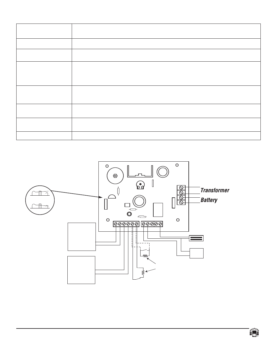
Application Diagram:
Fig. 1
VR1
NO
NO
GND
GND
FACP1 FACP2
STRIKE+
COM--
LOCK+
+ AUX --
TRIG INPUT
RESET
S
W
1
+
B
A
T
--
X
F
M
R
SW2:
12VDC - Open
24VDC - Closed
Normal Open
Access Control
Triggering
Device
Normal Open
Reset Device
2.2K EOL
(supplied)
MAG LOCK
NC
FACP
NO
FACP
{
}
Card
Reader
Fig. 1A - SW1
O PEN SWITCH
CLOSED SWITCH
Altronix is not responsible for any typographical errors.
140 58th Street, Brooklyn, New York 11220 USA, 718-567-8181, fax: 718-567-9056
website: www.altronix.com, e-mail: [email protected], Lifetime Warranty, Made in U.S.A.
IIAL125ULB - Rev. 012003
B03I
MEMBER