Maintenance, Led diagnostics, Terminal identification – Altronix AL600ULB Installation Instructions User Manual
Page 2
Altronix is not responsible for any typographical errors.
140 58th Street, Brooklyn, New York 11220 USA, 718-567-8181, fax: 718-567-9056
web site: www.altronix.com, e-mail: [email protected], Lifetime Warranty, Made in U.S.A.
IIAL600ULB Rev. 100302
H14M
MEMBER
Note: When used in fire alarm, burglar alarm or access control
applications, “AC Fail” relay must be used to provide a visual
indication of AC power on.
Maintenance:
Unit should be tested at least once a year for the proper
operation as follows:
Output Voltage Test: Under normal load conditions
the DC output voltage should be checked for proper
voltage level (refer to Power Supply Voltage Output
Specification chart).
Battery Test: Under normal load conditions check that the
battery is fully charged, check specified voltage both at the
battery terminal and at the board terminals marked
[+ BAT –] to ensure that there is no break in the battery connection wires.
Note: Maximum charging current under discharge is 0.7 amp.
Note: Expected battery life is 5 years; however, it is recommended changing batteries in 4 years or less if needed.
LED Diagnostics:
Red (DC) Green (AC) Power Supply Status
ON
ON
Normal operating condition.
ON
OFF
Loss of AC, Stand-by battery supplying power.
OFF
ON
No DC output
OFF
OFF
Loss of AC. Discharged or no stand-by battery. No DC output.
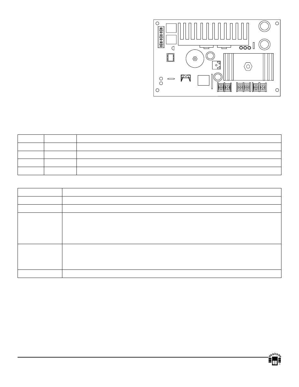
Terminal Identification:
Terminal Legend Function/Description
AC/AC
Connect 28VAC to these terminals from 2 connected in parallel transformers.
+ DC –
12VDC or 24VDC @ 6 amp continuous non-power limited output.
AC FAIL
NC, C, NO
Used to notify loss of AC power, e.g. connect to annunciator/alarm panel. Relay normally
energized when AC power is present. Contact rating 1 amp @ 30VDC. AC Fail condition will
report approximately one (1) minute after the loss of AC. To delay report for 6 hours cut jumper J1
on the Power Supply Board (AC trouble output delay option). If this mode is selected, the Power
Supply Board must be reset by removing all power to it for 30 seconds.
BAT FAIL
NC, C, NO
Used to indicate low battery condition, e.g. connect to alarm panel. Relay normally energized
when DC power is present. Contact rating 1 amp @ 30VDC. Low battery conditions will report
approximately 21VDC (24VDC output setting) or approximately 10.5VDC (12VDC output setting).
Battery presence detection will report approximately 1 minute after battery remains undetected
+ BAT –
Stand-by battery connections. Maximum charge current 0.7 amp.
+
DC ---
DC
AC
AC
+
BAT ---
OPEN = 24V SW1 CLOSED = 12V
RL2
RL3
AC
RLY1
PTC2
AC TROUBL
E
DELA
Y
OPTION
IC3
IC2
AC
FA
IL
NC C NO
BA
T
FA
IL
NC C NO
Fig. 1