Xfmr – Altronix AL300ULXD Installation Instructions User Manual
Page 2
- 2 -
AL300ULXD
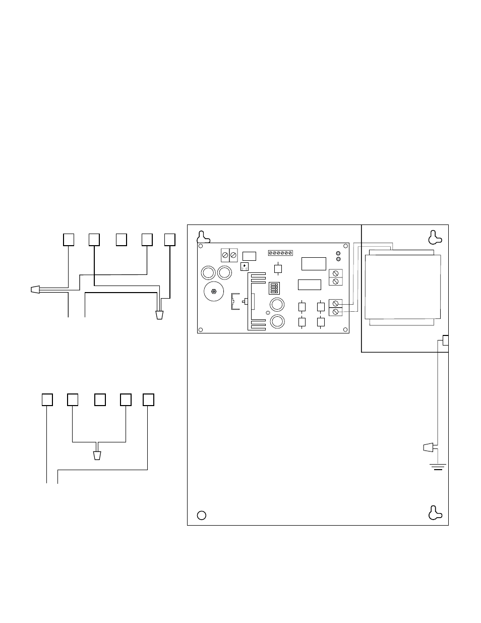
2. Connect input power to the transformer. Secure green wire lead to earth ground. (Fig. 1).
For 115VAC input: Connect Yellow and White leads from transformer primary to neutral.
Connect Blue and Black leads from transformer primary to line (Fig. 2).
For 230VAC input: Connect Blue and Yellow leads of transformer together.
Connect White lead from transformer to neutral.
Connect Black lead from transformer to line (Fig. 2).
Use 18 AWG or larger for all power connections (Battery, DC output).
Use 22 AWG to 18 AWG for power-limited circuits (AC Fail/Low Battery reporting).
Keep power-limited wiring separate from non power-limited wiring (115VAC 50/60Hz or 230 50/60Hz Input,
Battery Wires). Minimum 0.25” spacing must be provided.
3. Measure output voltage before connecting devices. This helps avoiding potential damage.
4. Connect devices to be powered to the terminals marked [+ DC –] (Fig. 1).
5. For Access Control applications batteries are optional. When batteries are not used, a loss of AC will result
in the loss of output voltage. When the use of stand-by batteries is desired, they must be lead acid or gel
type. Connect battery to terminals marked [– BAT +] (Fig. 1). Use two (2) 12VDC batteries connected in
series for 24VDC operation (battery leads included).
6. Connect appropriate signaling notification devices to AC Fail & Low battery (Fig. 1) supervisory relay outputs.
Green
Lead
(ground)
XFMR
+ DC --
AC FAIL NC NO C NC C NO LOW BAT
--
BA
T
+
DC
AC
1
234
ON
AC
AC
24V - SW1, 2 OFF
SW3, 4 ON
12V - SW1, 2 ON
SW3, 4 OFF
115VAC input
60 Hz 0.9 amp
230VAC input
60Hz 0.45 amp
power-limited
non
power
-limited
Fig. 1
5
4
3
2
1
BL
AC
K
YEL
LO
W
BL
UE
WHIT
E
LINE
NEUTRAL
115VAC Input
Fig. 3
- 230VAC Input
5
4
3
2
1
BL
AC
K
YEL
LO
W
BL
UE
WHIT
E
230VAC Input
Fig. 2
- 115VAC Input