Maintenance, Led diagnostics, Terminal identification – Altronix AL201ULB Installation Instructions User Manual
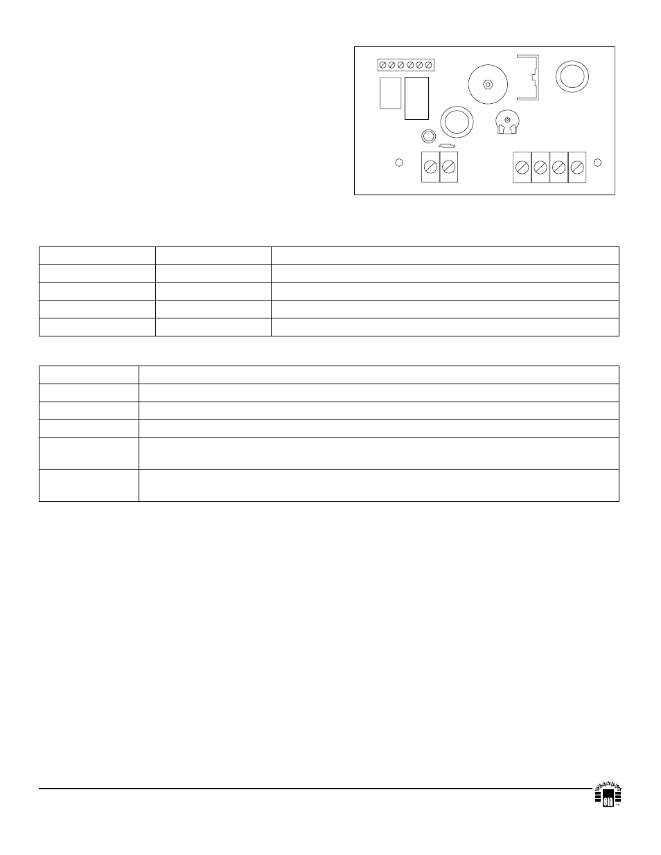
Page 2: Fig. 1
Maintenance:
Unit should be tested at least once a year for the proper
operation as follows:
Output Voltage Test: Under normal load conditions, the DC
output voltage should be checked for proper voltage
level (Power Supply Output Specifications Chart).
Battery Test: Under normal load conditions check that the
battery is fully charged, check specified voltage both at
battery terminal and at the board terminals marked [+ BAT -- ]
to insure there is no break in the battery connection wires.
Note: Maximum charging current under discharge is 400mA.
Note: Expected battery life is 5 years, however it is recom-
mended changing batteries in 4 years or less if needed.
LED Diagnostics:
Red (DC)
Green (AC)
Power Supply Status
ON
ON
Normal function
ON
OFF
Battery backup is powering output
OFF
ON
No DC output
OFF
OFF
Loss of AC. Discharged or missing stand-by battery. No DC output.
Terminal Identification:
Terminal Legend Function/Description
XFMR INPUT
Low voltage AC input.
+ DC OUT ---
Continuous positive (+) DC power output voltage. Common negative (-) output (ground).
+ BAT ---
Stand-by battery connections.
AC FAIL
NO, C, NC
Indicates loss of AC e.g connect audible device or alarm panel. Relay is normally
energized when AC power is present. Contact rating 1 amp @ 28VDC.
LOW BAT
NO, C, NC
Indicates low battery condition e.g connect audible device or alarm panel. Relay is normally
energized. Contact rating 1 amp @ 28VDC.
VR1
AC ON
XFMR INPUT
+ BAT ----
+ DC OUT ----
AC FAIL
NO C NC
LOW BAT
NO C NC
DC ON
MEMBER
Altronix is not responsible for any typographical errors.
140 58th Street, Brooklyn, New York 11220 USA, 718-567-8181, fax: 718-567-9056
website: www.altronix.com, e-mail: [email protected], Lifetime Warranty, Made in U.S.A.
IIAL201ULB - Rev. 041901
J17K
Fig. 1