Voltage selection configuration, Fig. 1, Terminal identification – Altronix ALTV244WPCB Installation Instructions User Manual
Page 3: Used on ptc models, 24vac output, 28vac output, Example: altv244wpcb), Yellow) (black) (black) (yellow)
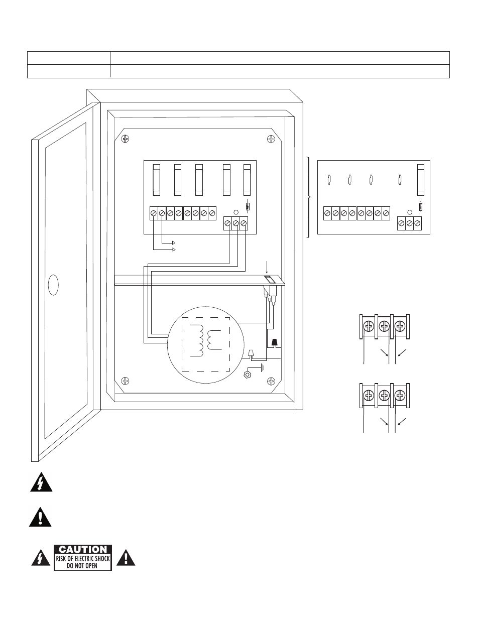
115VAC
Input
50/60 Hz.
Green
Lead
(Ground)
Power
Switch
White
Lead
Black
Lead
24VAC or 28VAC fused
output 1(Follow same
procedure using terminals
2P & N thru 4P & N fused
outputs 2 thru 4)
INPUT
1P
1N
2P
2N
3P
3N
4P
4N
LED
NP
S
1P, 2P, 3P, 4P = FUSED OUTPUTS
1N, 2N, 3N, 4N = COMMON OUTPUTS
Used on PTC Models
(example: ALTV244WPCB)
F1
F2
F3
F4
INPUT
1P
1N
2P
2N
3P
3N
4P
4N
LED
NP
S
1P, 2P, 3P, 4P = FUSED OUTPUTS
1N, 2N, 3N, 4N = COMMON OUTPUTS
F1
F2
F3
F4
XFMR*
MA
IN FUS
E
MA
IN FUS
E
- 3 -
Fig. 1
The lightning flash with arrow head symbol within an equilateral triangle is intended to alert the user to the
presence of an insulated “DANGEROUS VOLTAGE” within the products enclosure that may be of sufficient
magnitude to constitute an electric shock.
The exclamation point within an equilateral triangle is intended to alert the user to the presence of important
operating and maintenance (servicing) instructions in the literature accompanying the appliance.
CAUTION: To reduce the risk of electric shock do not open enclosure. There are
no user serviceable parts inside. Refer servicing to qualified service personnel.
NP
S
NP
S
24VAC
Output
(Yellow)
(Black)
(Black)
(Yellow)
28VAC
Output
Voltage Selection
Configuration
Terminal Identification:
PD4/PD4CB - Distribution Module
1P - 4P
Positive AC output.
1N - 4N
Negative AC output.