Maintenance, Led diagnostics, Terminal identification – Altronix AL300ULB Installation Instructions User Manual
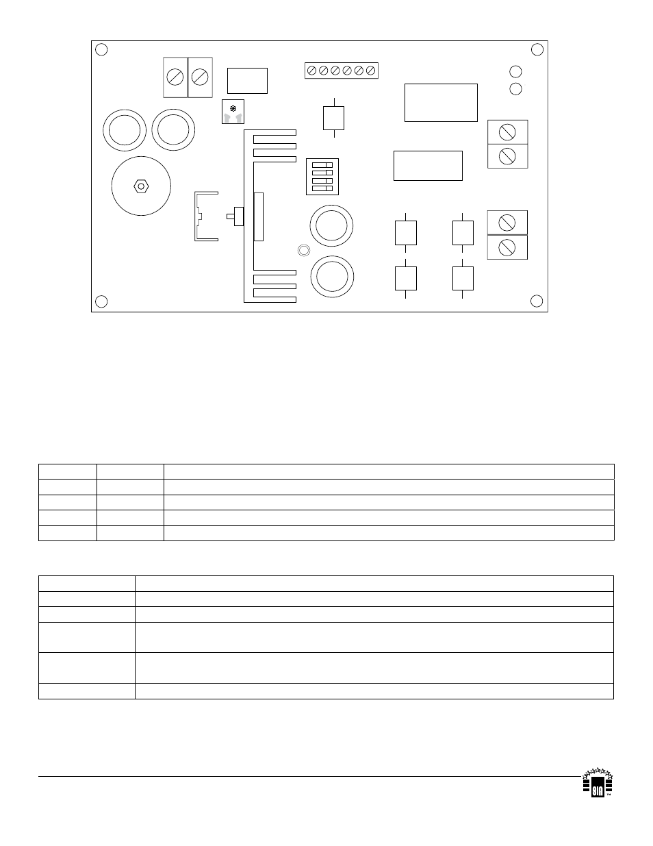
Page 2: Fig. 1
Maintenance:
Unit should be tested at least once a year for the proper operation as follows:
Output Voltage Test: Under normal load conditions, the DC output voltage should be checked for proper voltage level
(refer to Power Supply Output Specifications Chart).
Battery Test: Under normal load conditions check that the battery is fully charged, check specified voltage both at the
battery terminal and at the board terminals marked [- BAT +] to ensure that there is no break in the battery connection wires.
Note: Maximum charging current under discharge is 0.6 amp.
Note: Expected battery life is 5 years; however, it is recommended changing batteries in 4 years or less if needed.
LED Diagnostics:
Red (DC) Green (AC) Function/Description
ON
ON
Normal operating condition.
ON
OFF
Loss of AC, Stand-by battery supplying power.
OFF
ON
No DC output.
OFF
OFF
Loss of AC. Discharged or no stand-by battery. No DC output.
Terminal Identification:
Terminal Legend Function/Description
AC/AC
Low voltage AC input 28VAC / 100VA.
+ DC ---
12VDC / 24VDC @ 2.5 amp continuous supply current.
AC FAIL
N.C., N.O., C
Used to notify loss of AC power, e.g. connect to audible device or alarm panel. Relay normally
energized when AC power is present. Contact rating 1 amp @ 28VDC.
LOW BAT
N.C., C, N.O.
Used to indicate low battery condition, e.g. connect to alarm panel. Relay normally energized when
DC power is present. Contact rating 1 amp @ 28VDC.
--- BAT +
Stand-by battery connections. Maximum charge current 600mA.
Altronix is not responsible for any typographical errors.
140 58th Street, Brooklyn, New York 11220 USA, 718-567-8181, fax: 718-567-9056
web site: www.altronix.com, e-mail: [email protected], Lifetime Warranty, Made in U.S.A.
IIAL300ULB - Rev. 09062012
H14M
+ DC --
AC FAIL NC NO C NC C NO LOW BAT
--
BA
T
+
DC
AC
123
4
ON
AC AC
24V - SW1, 2 OFF
SW3, 4 ON
12V - SW1, 2 ON
SW3, 4 OFF
Fig. 1
MEMBER