Maintenance, Fig. 1a fig. 1 – Altronix ACM4CB Installation Instructions User Manual
Page 4
- 4 -
ACM4 series
(c) FACP Signaling Circuit input trigger:
Connect the positive (+) and negative (-) from the FACP signaling circuit output to the terminals marked [+ INP -].
Connect the FACP EOL to the terminals marked [+ RET -] (polarity is referenced in an alarm condition).
Jumper J3 must be cut (Fig. 3, pg. 6).
6.
FACP Dry form “C” output (Fig. 1a, pg. 4):
Connect desired device to be triggered by the unit’s dry contact output to the terminals marked [NO] and [C]
FACP for normally open output or the terminals marked [NC] and [C] FACP for normally closed output.
7.
Installation of tamper switch (Not Included):
Mount UL Listed tamper switch (Sentrol model 3012 or equivalent) at the top of the enclosure. Slide the tamper
switch bracket onto the edge of the enclosure approximately 2” from the right side.
Connect tamper switch wiring to the Listed Access Control Panel input or the appropriate UL Listed reporting device,
to activate alarm signal when the door of the enclosure is open.
Maintenance:
Unit should be tested at least once a year for the proper operation. Voltage on each output has to be tested for both
trigger and non-trigger states and operation of FACP interface has to be simulated.
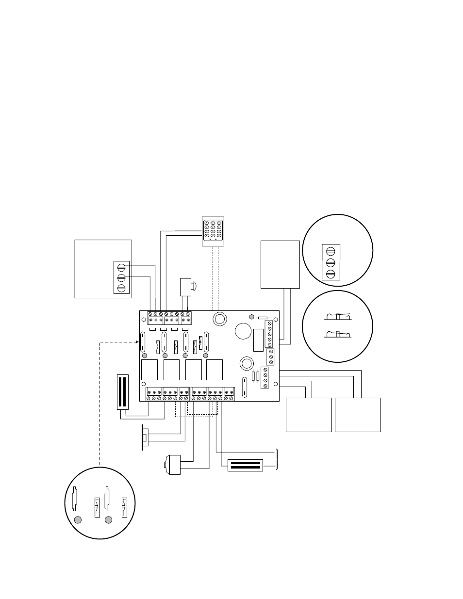
Typical Application Diagram:
NC C NO COM
OUTPUT1
NC C NO COM
OUTPUT2
NO
C
NC
FACP
---
+
---
+
Power
Control
+ INP -
--
T
+ RET -
--
INTERF
ACE
LED1
SW1
SW2
SW3
SW4
LED2
LED3
LED4
TRIGGER
INPUT
TRG
NC C NO COM
OUTPUT3
NC C NO COM
OUTPUT4
J2 J1
J3
ACM4
ACCESS POWER
CONTROLLER
LED1
SW1
SW2
LED2
IN GND
2
IN GND
1
IN GND
3
IN GND
4
NC
NO
C
KEYPAD
NORMALLY OPEN
N.O. DOOR
RELEASING
DEVICE
ACCESS CONTROL
PANEL
OUTPUT
RELAY
MAG.
LOCK
MAG.
LOCK
ELECTRIC
STRIKE
ELECTROMAGNETIC
DOOR HOLDERS
LISTED
AC or DC
ACCESS CONTROL
POWER SUPPLY
(optional)
FACP
(Fire Alarm
Control Panel)
LISTED
AC or DC
ACCESS CONTROL
POWER SUPPLY
(req’d)
UL Listed Power-Limited Power Supply
For this application
corresponding fuse
must be removed.
(ACM4 only)
FACP Interface Enabled
FACP Interface Disabled
SW1-SW4
ACM4CB
FACP Dry
Form "C"
Output
NO C NC
FACP
3A
10A
3A
3A
3A
Keep power limited wiring separate from non-power limited.
Use minimum .25" spacing.
Fig. 1a
Fig. 1