1c - led(s) 1-16: p o w er indicators. f ront rear – Altronix HubWay 8D Installation Instructions User Manual
Page 4
- 4 -
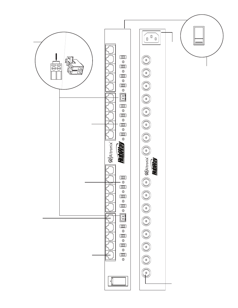
HubWay Passive Unit
1
2
3
4
C
H
1
-4
C
H
5
-8
28
VA
C
O
FF
24
VA
C
+
D
AT
A
-
1-
8
+
D
AT
A
-
9-
16
5
6
7
8
9
10
11
12
C
H
9
-1
2
28
VA
C
O
FF
24
VA
C
13
14
15
16
C
H
1
3-
16
A
C
P
O
W
ER
16
15
14
13
12
11
10
9
8
7
6
5
4
3
2
1
O
F
F
R
E
S
E
T
1a
- Channels 1-8 (HubW
a
y8D) or
Channels 1-16 (HubW
a
y16D):
CA
T
-5
or higher str
uctured cab
le to
V
ideo/Balun Combiners at
cameras 1-8 or 1-16.
When using
an optional HubSat4D an
y of the
outputs can be utilized for data
transmission to PTZ’
s
1f
- BNC
Connector:
V
ideo
outputs
to head end
equipment (D
VR).
1d
- Output v
olta
g
e
switc
hes:
Selects
24V
A
C/28V
A
C/OFF
for
each output.
1b
- Channels 1-4,
Channels 5-8,
Channels 9-12 & Channels 13-16:
CA
T
-5
or higher str
uctured cab
le from optional HubSat4S enab
les
video transmission from up to four (4) cameras.
1g
- IEC 320 Connector:
115V
A
C
60Hz
/230V
A
C
50/60Hz (g
rounded
line cord included).
F
ig
. 1
1e
- Data:
Remo
v
ab
le
ter
minal
b
locks for RS422/
RS485 input from head end
equipment (D
VR) for PTZ control.
+ --
D
a
ta
i
n
p
u
t
fr
o
m
H
e
a
d
E
n
d
E
q
u
ip
m
e
n
t
(D
V
R
).
T
o
p
V
ie
w
1h
- Input
V
olta
g
e Switc
h:
Selects
115V
A
C
60Hz/230V
A
C 50/60Hz
(s
witch is located on the left
side of the unit).
1
1
5
V
A
C
2
2
0
V
A
C
1c
- LED(s) 1-16:
P
o
w
er
indicators.
F
ront
Rear