Led diagnostic table, Terminal identification, Typical application diagrams – Altronix MOM5C Installation Instructions User Manual
Page 2: Fig. 2
LED Diagnostic Table:
LED
ON
OFF
Power (Green)
Normal operation.
Loss of power to MOM5.
Trigger (Green) MOM5 triggered (alarm condition).
MOM5 in stand-by (non-alarm condition).
Outputs (Red)
Output tripped due to a short circuit or overload condition. Normal operation.
Terminal Identification:
Terminal Legend
Function/Description
-- DC INPUT +
12VDC or 24VDC from power supply.
TRIGGER
This circuit is supervised by a 2.2K EOL resistor. Initiating a short or open will
cause power to be dropped to all terminals marked [Pos. (+) DC Output (Stand-by)]
and supply power to all terminals marked [Pos (+) DC Output (Alarm)].
-- INPUT +
Applying voltage to terminals marked [-- Input +] from the FACP signaling circuit in
polarity shown will yield the same results as initiating trigger (mentioned above).
NEG1 thru NEG5
Supplies constant negative (-) voltage.
POS (+) DC OUTPUT
Supplies positive (+) voltage when either input trigger is activated.
(ALARM)
POS (+) DC OUTPUT
Supplies positive (+) voltage in normal condition.
(STANDBY)
Power is removed when either input trigger is activated.
NC, C, NO
When the MOM5 is triggered the terminals marked [C and NO] will close and the
DRY OUTPUT
terminals marked [C and NC] will open. This output is used to trip auxiliary devices.
e.g. HVAC Shutdown, Elevator Recall etc...
NC, C, NO
Form “C” contacts used for signaling when no voltage is present at [-- DC input +]
POWER FAIL
terminals. Under normal conditions, terminals marked [NO and C] are open,
and terminals marked [NC and C] are closed. A occurrence of trouble condition causes
terminals marked [NO and C] to closed and [NC and C] to open.
- 2 -
MOM5C
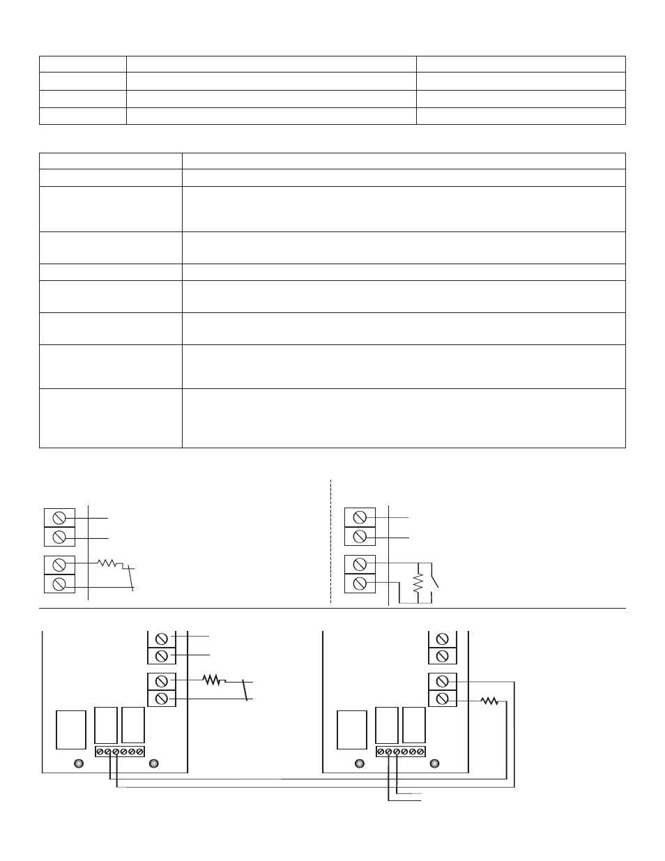
Fig. 1 - MOM5C module shown with wet and/or dry normally
closed trigger inputs (Non-Latching):
Typical Application Diagrams:
T
R
IG
G
E
R
--
IN
P
U
T
+
EOL 2.2K
(+)
(-)
DC VOLTAGE INPUT
FROM FACP SIGNALING
OUTPUT OR ACCESS
CONTROL DEVICE
NORMALLY CLOSED (NC)
INPUT FROM FACP
OR ACCESS CONTROL DEVICE
T
R
IG
G
E
R
--
IN
P
U
T
+
E
O
L
2
.2
K
(+)
(-)
DC VOLTAGE INPUT
FROM FACP SIGNALING
OUTPUT OR ACCESS
CONTROL DEVICE
NORMALLY OPEN (NO)
INPUT FROM FACP
OR ACCESS CONTROL DEVICE
MOM5C module shown with wet and/or dry normally open
trigger inputs (Non-Latching):
Fig. 2
- Two (2) or more MOM5C modules shown with wet and/or dry normally closed trigger inputs (Non-Latching):
TRIGGER
LED
POWER
ON LED
T
R
IG
G
E
R
--
IN
P
U
T
+
EOL 2.2K
EOL 2.2K
NORMALLY CLOSED (NC)
INPUT FROM FACP OR
ACCESS CONTROL DEVICE
DC VOLTAGE INPUT FROM
FACP SIGNALING
OUTPUT OR ACCESS
CONTROL DEVICE
(+)
(--)
TO TRIGGER INPUT
OF NEXT MOM5
NC C NO
DRY OUTPUT
NC C NO
POWER FAIL
TRIGGER
LED
POWER
ON LED
T
R
IG
G
E
R
--
IN
P
U
T
+
NC C NO
DRY OUTPUT
NC C NO
POWER FAIL