Altronix OLS75 Installation Instructions User Manual
Page 2
LED Diagnostics:
Red (DC) Green (AC) Power Supply Status
ON
ON
Normal operating condition.
ON
OFF
Loss of AC, Stand-by battery supplying power.
OFF
ON
No DC output. Short circuit or thermal overload condition.
OFF
OFF
Loss of AC. Discharged or no stand-by battery. No DC output.
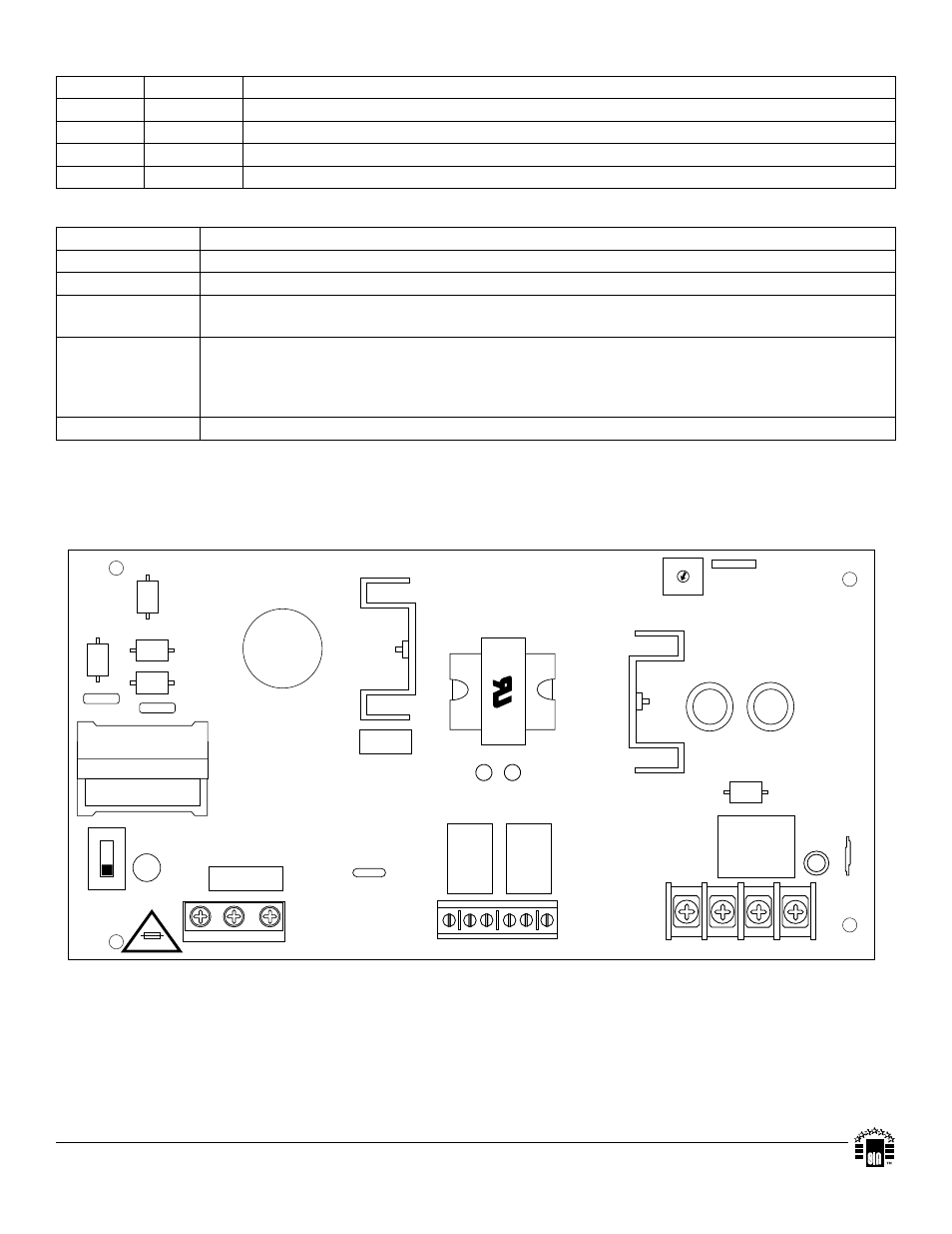
Terminal Identification:
Terminal Legend Function/Description
L, G, N
Connect 115VAC/230VAC to these terminals: L to Hot, N to Neutral, G to ground.
– DC +
12VDC / 24VDC @ 2.5 amp continuous supply current.
AC FAIL
NC, C, NO
Used to notify loss of AC power, e.g. connect to audible device or alarm panel. Relay normally
energized when AC power is present. Contact rating 1 amp @ 115VAC / 28VDC
Low Battery
NC, C, NO
Used to indicate low battery condition, e.g. connect to alarm panel. Relay normally energized when
DC power is present. Contact rating 1 amp @ 115VAC / 28VDC
Low battery threshold:12VDC output threshold set @ approximately 10.5VDC, 24VDC output
threshold set @ approximately 21VDC.
– BAT +
Stand-by battery connections. Maximum charge rate 0.5 amp.
L
G
N
OFF ON
OPEN - 24VDC
CLOSED - 12VDC
LOW BA
T
NC C NO NC C NO
AC FAIL
--- BAT +
--- DC +
AC DC
5A 250V
Altronix is not responsible for any typographical errors. Product specifications are subject to change without notice.
140 58th Street, Brooklyn, New York 11220 USA, 718-567-8181, fax: 718-567-9056
website: www.altronix.com, e-mail: [email protected], Lifetime Warranty, Made in U.S.A.
IIOLS75 - Rev. 010704
E13M
MEMBER