Altronix LPS3R Installation Instructions User Manual
Lps3/lps3r - linear power supply/charger, Overview, Specifications: input
Overview:
LPS3/LPS3R linear power supply/chargers will convert a low voltage AC input to a low voltage 12VDC/24VDC output.
These power supplies are specifically designed to provide to power needed by the most demanding security and access
control applications.
Specifications:
Input:
• 16VAC or 28VAC
(refer to voltage output/transformer selection chart).
Output:
• 12VDC/24VDC selectable output.
• 2.5 amp continuous supply current.
• Filtered and electronically regulated output.
• Thermal overload and short circuit protection.
Battery Backup:
• Built-in charger for sealed lead acid or gel type batteries.
• Maximum charge current 500mA.
• Automatic switch over to stand-by battery.
• Fused battery protection (circuit breaker available).
• Includes battery leads.
Visual Indicators:
• AC input and DC output LED indicators.
Board Dimensions (approximate):
6.5”L x 3.5”W x 1.75”H
Specified at 25˚ C ambient.
Voltage Output/Transformer Selection Table:
Output Voltage
Switch
Transformer Requirements
Position
(Recommended Altronix Part #’s)
12VDC
Closed
16VAC / 56 VA (T1656).
24VDC
Open
24VAC or 28VAC / 100VA
(Altronix model T2428100)
Note: Transformers with higher VA ratings may be used.
Installation Instructions:
The LPS3/LPS3R should be installed in accordance with The National Electrical Code and all applicable Local
Regulations.
1. Mount the LPS3/LPS3R in desired location / enclosure.
2. Set DC output voltage using switch SW2 (refer to voltage output/transformer selection table).
3. Connect proper transformer to terminals marked AC (refer to voltage output/transformer selection table).
4. Measure output voltage before connecting devices. This helps avoid potential damage.
5. Connect devices to be powered to terminals marked [ --- - DC +].
6. When the use of stand-by batteries are desired, they must be lead acid or gel type.
Connect battery to terminals marked [+ BAT --- ] on the unit (battery leads included).
Use two (2) 12VDC batteries connected in series for 24VDC operation.
7. When batteries are not used a loss of AC will result in the loss of output voltage.
8. Connect supervisory trouble reporting devices to outputs marked [AC Fail] (LPS3R only).
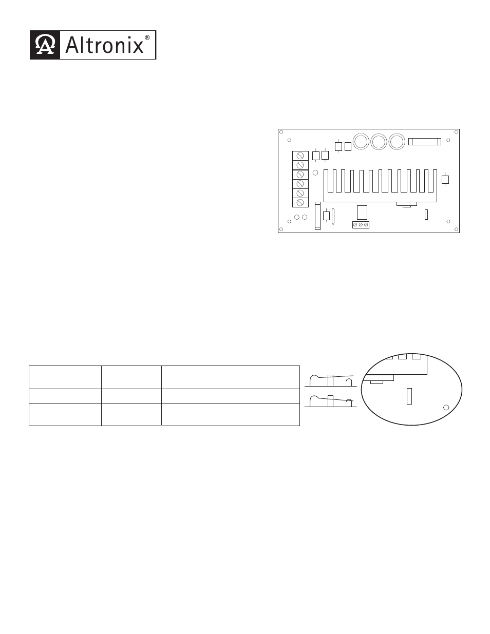
LPS3/LPS3R - Linear Power Supply/Charger
AC
DC
A
C
AC FAIL
CONTACTS
A
C
--
D
C
+
--
B
A
T
+
NC C NO
SW1
12V-CLOSED
24V-OPEN
Supervision:
• LPS3R is the same as LPS3 w/ AC Fail
supervision (Form “C” contacts.)
OPEN SWITCH
CLOSED SWITCH
Switch Detail
AC
DC
A
C
AC FAIL
CONTACTS
A
C
--
D
C
+
--
B
A
T
+
NC C NO
SW1
12V-CLOSED
24V-OPEN
Fig. 1