Altronix VertiLine6D Installation Instructions User Manual
Page 4
- 4 -
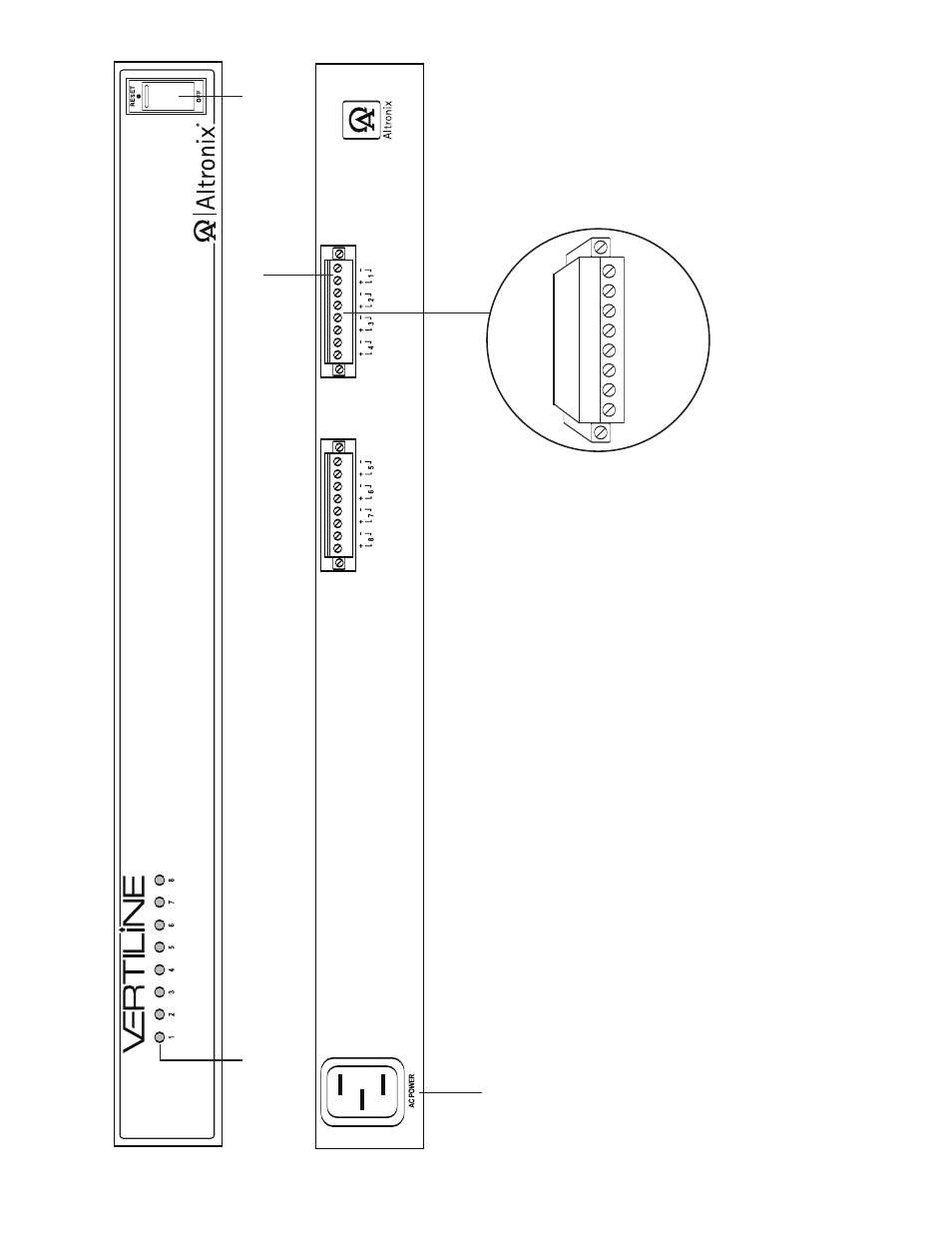
Vertiline3D/VertiLine6D
1a
LED(s)
1-8:
P
o
w
er
LED indicators.
1b
P
o
w
er
Outputs:
12VDC
or 24VDC.
1c
Illuminated
master po
w
er disconnect cir
cuit br
eak
er (switc
h):
•
OFF
position Circuit break
er tripped Switch not illuminated.
•
RESET (ON) position Switch illuminated.
1d
IEC
320 Connector:
115V
A
C
60Hz (g
rounded line cord included).
1e
Remo
vab
le
T
erminal Bloc
k.
F
ig
. 1
V
er
tiline3D
and
V
er
tiline6D (fr
ont)
V
er
tiline3D and
V
er
tiline6D (r
ear)
1a
1b
1c
1d
1e
Remo
vab
le
T
erminal
Bloc
k
See also other documents in the category Altronix Accessories for electrical:
- NetWay3012 Installation Instructions (2 pages)
- HubWay 16Di Data Sheet (2 pages)
- Maximal77 Installation Instructions (20 pages)
- HubWay Dvi Data Sheet (1 page)
- HubWay Av2 Data Sheet (1 page)
- PD4CB Installation Instructions (1 page)
- ACM4CB Data Sheet (2 pages)
- VertiLine63D Data Sheet (2 pages)
- eBridge16CR Installation Instructions (8 pages)
- LPS3WP12 Data Sheet (2 pages)
- VertiLine246D Data Sheet (2 pages)
- T24130D Data Sheet (1 page)
- eBridge1PCRTX Data Sheet (2 pages)
- RB5 Installation Instructions (1 page)
- Tempo2 Data Sheet (1 page)
- BC600G Data Sheet (1 page)
- eBridge1CRT Data Sheet (2 pages)
- AL400ULB Data Sheet (1 page)
- PT2724 Installation Instructions (8 pages)
- OLS180 Installation Instructions (2 pages)
- HubWay 8CD Data Sheet (2 pages)
- AL175ULB Data Sheet (1 page)
- StrikeIt2 Installation Instructions (8 pages)
- LPD Data Sheet (1 page)
- eBridge4SK Installation Instructions (8 pages)
- LPS3AC Installation Instructions (2 pages)
- T2428100 Data Sheet (1 page)
- TP1650 Data Sheet (1 page)
- T2885D Data Sheet (1 page)
- T2428175 Installation Instructions (1 page)
- T1656 Installation Instructions (1 page)
- SMP3 Data Sheet (1 page)
- RBR1224 Data Sheet (1 page)
- HubWay LD16D Data Sheet (2 pages)
- eFlow102NX16D Installation Instructions (16 pages)
- T24175C Data Sheet (1 page)
- Maximal5D Data Sheet (2 pages)
- Maximal7 Installation Instructions (16 pages)
- HubWay 8CDS Data Sheet (2 pages)
- eFlow4NX8D Installation Instructions (16 pages)
- MOM5C Data Sheet (1 page)
- eBridge16PCRX Installation Instructions (8 pages)
- HubWay EX16SP Data Sheet (2 pages)
- T24130C Installation Instructions (1 page)
- Maximal5 Data Sheet (2 pages)