Fig. 5 - timed door strike, Fig. 2 - guard tour supervisory timer, Fig. 6 - timed shunt for a door – Altronix DTMR1 Installation Instructions User Manual
Page 2: Fig. 3 - swinger eliminator, Fig. 7 - bell cut off timer, Fig. 8 - closed circuit trigger option, Fig. 4 - delay timer, Trg --- + power supply + -- closed circuit contact
CUT JI FOR REPEAT J1
MADE IN USA
BKLYN, NY 11220
1
2
3
4
ON
6062
TIMER
TRIG CONTROL
4
12V /
24V
3
SEC. /
MIN.
2
RELAY CONTROL
1
TRG
---
+
N
O
C
NC
1
AL
TRONIX CORP
.
ON
OFF
15
CUT J3 FOR RESET
ON POWER-UP
J3
CUT J2 FOR DELAY PULSE J2
45
60
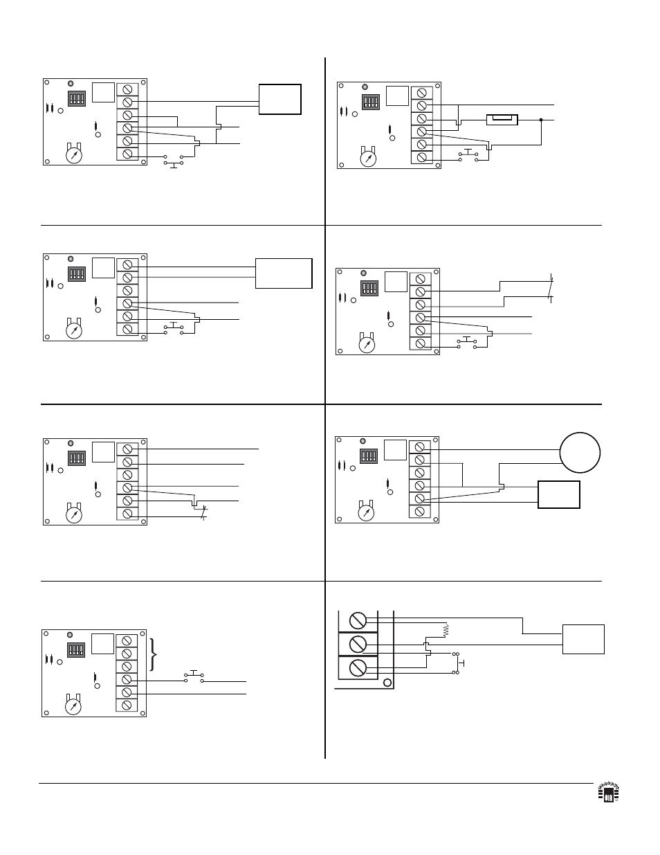
DTMR1 Typical Applications
Fig. 1 - Timed Door Annunciator:
For this application Switch #1 and Switch #4 should be
in the OFF position.
Fig. 5 - Timed Door Strike:
For this application Switch #1 should be in the OFF
position and Switch #4 should be in the ON position.
Fig. 2 - Guard Tour Supervisory Timer:
For this application Switch #1 and Switch #4 should be
in the OFF position.
Fig. 6 - Timed Shunt for a Door:
Use to bypass alarm
contacts.
For this application Switch #1 should be in the OFF
position and Switch #4 should be in the ON position.
CHIME
Pos (+) and Neg (-)
terminals constant 12
or 24VDC
+
--
Normally open door contacts
CUT JI FOR REPEAT J1
MADE IN USA
BKLYN, NY
11220
1
2
3
4
ON
6062
TIMER
TRIG CONTROL
4
12V /
24V
3
SEC. /
MIN.
2
RELAY CONTROL
1
TRG
---
+
N
O
C
NC
1
AL
TRONIX CORP
.
ON
OFF
15
CUT J3 FOR RESET
ON POWER-UP
J3
CUT J2 FOR DELAY PULSE J2
45
60
DIALER OR
TRANSMITTER
Pos (+) and Neg (-)
terminals constant 12
or 24VDC
+
--
Normally open switch contacts
CUT JI FOR REPEAT J1
MADE IN USA
BKLYN, NY
11220
1
2
3
4
ON
6062
TIMER
TRIG CONTROL
4
12V /
24V
3
SEC. /
MIN.
2
RELAY CONTROL
1
TRG
---
+
N
O
C
NC
1
AL
TRONIX CORP
.
ON
OFF
15
CUT J3 FOR RESET
ON POWER-UP
J3
CUT J2 FOR DELAY PULSE J2
45
60
Pos (+) and
Neg (-) termi-
nals constant
12 or 24VDC
+
--
Normally open door contacts
Door Strike
CUT JI FOR REPEAT J1
MADE IN USA
BKLYN, NY
11220
1
2
3
4
ON
6062
TIMER
TRIG CONTROL
4
12V /
24V
3
SEC. /
MIN.
2
RELAY CONTROL
1
TRG
---
+
N
O
C
NC
1
AL
TRONIX CORP
.
ON
OFF
15
CUT J3 FOR RESET
ON POWER-UP
J3
CUT J2 FOR DELAY PULSE J2
45
60
Pos (+) and Neg (-)
terminals constant 12
or 24VDC
+
--
Normally open switch contacts
Door Contacts
Protective Circuit
+
--
+
--
Fig. 3 - Swinger Eliminator:
For this application Switch #1 should be in the OFF
position and Switch #4 should be in the ON position.
Fig. 7 - Bell Cut Off Timer:
For this application Switch #1 should be in the ON posi-
tion and Switch #4 is not used in this application.
CUT JI FOR REPEAT J1
MADE IN USA
BKLYN, NY
11220
1
2
3
4
ON
6062
TIMER
TRIG CONTROL
4
12V /
24V
3
SEC. /
MIN.
2
RELAY CONTROL
1
TRG
---
+
N
O
C
NC
1
AL
TRONIX CORP
.
ON
OFF
15
CUT J3 FOR RESET
ON POWER-UP
J3
CUT J2 FOR DELAY PULSE J2
45
60
Control Panel
12 or 24VDC
BELL
OUTPUT
BELL OR
SIREN
CUT JI FOR REPEAT J1
MADE IN USA
BKLYN, NY
11220
1
2
3
4
ON
6062
TIMER
TRIG CONTROL
4
12V /
24V
3
SEC. /
MIN.
2
RELAY CONTROL
1
TRG
---
+
N
O
C
NC
1
AL
TRONIX CORP
.
ON
OFF
15
CUT J3 FOR RESET
ON POWER-UP
J3
CUT J2 FOR DELAY PULSE J2
45
60
Pos (+) and Neg (-)
terminals constant 12
or 24VDC
+
--
Protective
Circuit
Closed Circuit
Zone on Control Panel
+
--
Fig. 8 - Closed Circuit Trigger Option:
TRG
---
+
Power
Supply
+
--
closed
circuit contact
Fig. 4 - Delay Timer:
Use for Door Ajar Alarm,
Delayed Activation of Digital Dialer, Defrost Cycle
Timer, etc...
For this application Switch #1 should be in the ON
position and Switch #4 is not used in this application.
CUT JI FOR REPEAT J1
MADE IN USA
BKLYN, NY
11220
1
2
3
4
ON
6062
TIMER
TRIG CONTROL
4
12V /
24V
3
SEC. /
MIN.
2
RELAY CONTROL
1
TRG
---
+
N
O
C
NC
1
AL
TRONIX CORP
.
ON
OFF
15
CUT J3 FOR RESET
ON POWER-UP
J3
CUT J2 FOR DELAY PULSE J2
45
60
Pos (+) and Neg (-)
terminals constant
12 or 24VDC
+
--
Use appropriate contacts to reporting devices
Normally open triggering device
1K resistor
For this application a 1K (1,000 ohm) resistor must be
installed as shown. (resistor not supplied)
Altronix is not responsible for any typographical errors.
140 58th Street, Brooklyn, New York 11220 USA, 718-567-8181, fax: 718-567-9056
website: www.altronix.com, e-mail: [email protected], Lifetime Warranty, Made in U.S.A.
IIDTMR1
J30C
MEMBER