Altronix PD4UL Installation Instructions User Manual
Pd4ul, Overview, Specifications
Overview:
The PD4UL is a UL Listed Sub-Assembly power distribution module, designed to convert a single DC input into
four (4) individually fuse protected outputs.
Specifications:
INPUT
1P
1N
2P
2N
LED
1P, 2P, 3P, 4P = FUSED OUTPUTS
1N, 2N, 3N, 4N = COMMON OUTPUTS
F1
3P
3N
4P
4N
F2
F3
F4
N
P
S
DC
Positive (+)
Input
DC
Negative ( --- )
Input
PD4UL
POWER DISTRIBUTING UNIT
Fire Alarm System Power Supply Unit Also suitable for use as a Access Control System Unit Subassembly
.
9B98
Refer to Installation Instructions IIPD4UL - REV
. 030802
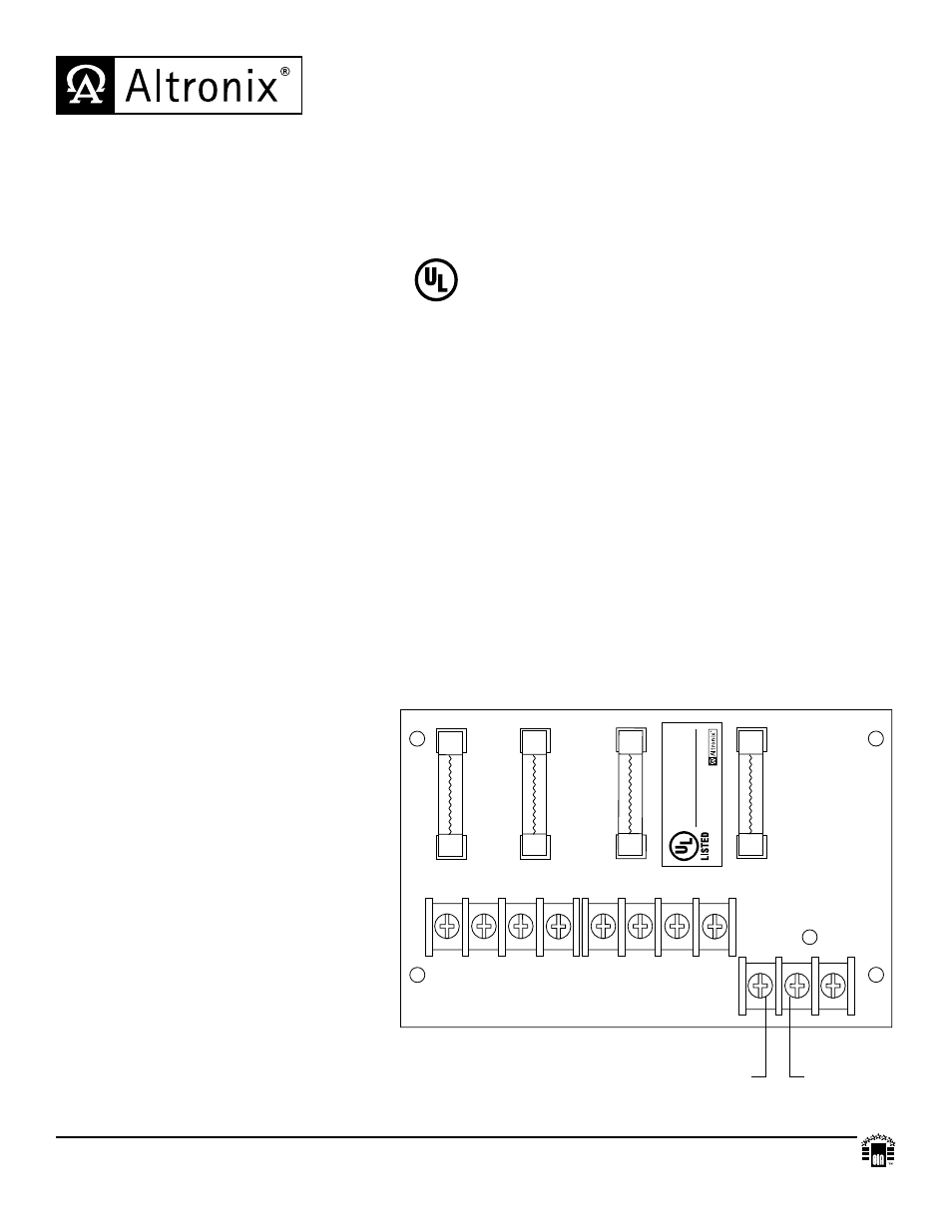
Fig. 1
(#P) Positive DC outputs
(#N) Negative DC outputs
Note: DC outputs are power limited only if
power limited power supply is employed.
Caution: To avoid risk of electric shock
or fire hazard replace fuses with the same
type and rating, 3.5 amp/250V.
Do not expose to rain or moisture.
PD4UL - UL Listed Sub-Assembly
Power Distribution Module
Altronix is not responsible for any typographical errors.
140 58th Street, Brooklyn, New York 11220 USA, 718-567-8181, fax: 718-567-9056
website: www.altronix.com, e-mail: [email protected], Lifetime Warranty, Made in U.S.A.
IIPD4UL - Rev. 051311
E13K
Agency Listings:
• UL Listed Sub-Assembly for Access
Control System Units (UL 294) and
for Power Supplies for Fire Protective
Signaling Systems (UL 1481).
Input:
• 12VDC or 24VDC up to 10 amp.
Outputs:
• Four (4) individually fuse protected outputs @ 2.5 amp
per output max. current (total output current should not
exceed max. current rating of power supply employed).
Fuse Ratings:
• Fuses are rated @ 3.5A/250V.
Visual Indicators:
• Power on green LED indicator.
Board Dimensions (approximate):
5.25”L x 3.25”W x 1”H
Installation Instructions:
Wiring methods shall be in accordance with the National Electrical Code/NFPA 70/NFPA 72/ANSI, and with all local
codes and authorities having jurisdiction. Product is intended for indoor use only and should be installed
by qualified personnel.
1. Refer to Sub Assembly Installation Instruction for mounting Rev. MS042511.
2. Connect the desired power supply output to terminals marked [INPUT] (Fig. 1).
Note: Left terminal is NEG. (-) and right terminal is POS. (+) (Fig. 1).
3. Measure output voltage before connecting devices. This helps avoid potential damage.
4. Connect devices to be powered to terminal pairs 1 to 4, marked [1P - 1N thru 4P - 4N]. All terminals with common
suffix P “1P, 2P...” are same polarity.
Note: This product is a UL Listed Sub-Assembly for use with Altronix UL Listed power supplies
as indicated in the installation manuals for the power supply.
MEMBER
LISTED
SECURITY
SIGNALING