Altronix RB610 Installation Instructions User Manual
Rb610 - break away relays, Specifications, Installation instructions
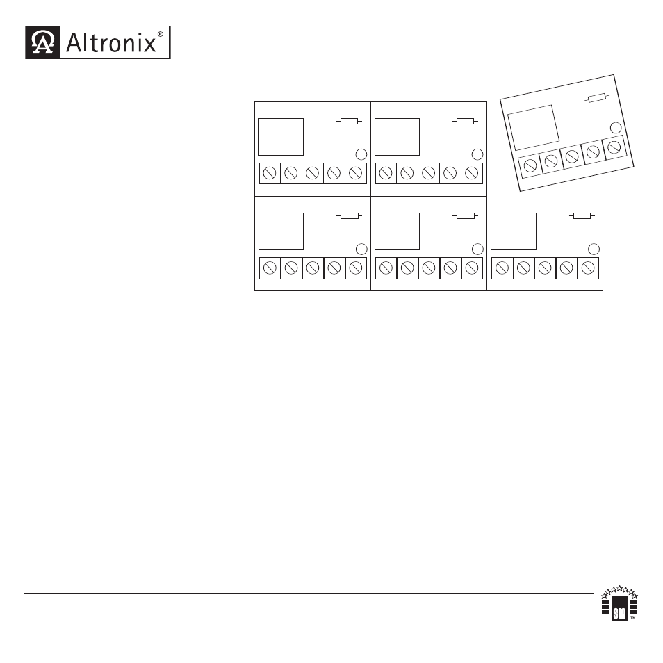
RB610 - Break Away Relays
Specifications:
• Each cluster contains six (6)
relay modules which can
easily be separated.
• 12VDC or 24VDC
selectable operation.
• Current draw 50mA.
• 10 amp/120VAC or 28VDC
SPDT contacts.
• Screw terminals accommodate up to 12 gauge wire.
Board dimensions: 2"L x 1.5"W x 1"H
Installation Instructions:
1. In order to break the relay cluster apart (if desired) put a pencil on a flat surface,
position the scoring line on top of the pencil and push lightly. Relay should easily
breakaway from cluster.
2. Connect trigger input or voltage source to screw terminals marked [POS (+) & NEG (-)].
(Unit is factory set for 12VDC operation - cut jumper for 24VDC operation).
3. Connect screw terminals marked [NC] (Normally Closed) or [NO]
(Normally Open) and [C] (Common)] to operate desired devices.
RB610
FACTORY SET 12 VDC
CUT JMPR FOR 24 VDC
NC
NO
C
+
---
JMPR
RB610
FACTORY SET 12 VDC
CUT JMPR FOR 24 VDC
NC
NO
C
+
---
JMPR
RB6
10
FAC
TOR
Y S
ET 1
2 VD
C
CUT
JMP
R F
OR
24 V
DC
NC
NO
C
+
---
JMP
R
RB610
FACTORY SET 12 VDC
CUT JMPR FOR 24 VDC
NC
NO
C
+
---
JMPR
RB610
FACTORY SET 12 VDC
CUT JMPR FOR 24 VDC
NC
NO
C
+
---
JMPR
RB610
FACTORY SET 12 VDC
CUT JMPR FOR 24 VDC
NC
NO
C
+
---
JMPR
Altronix is not responsible for any typographical errors. Product specifications are subject to change without notice.
140 58th Street, Brooklyn, New York 11220 USA, 718-567-8181, fax: 718-567-9056
website: www.altronix.com, e-mail: [email protected], Lifetime Warranty, Made in U.S.A.
IIRB610 - Rev. 012907
B11I
MEMBER