1b - led(s) 1-8: p o w er indicators. rear – Altronix HubWay 8CDS Installation Instructions User Manual
Page 4
- 4 -
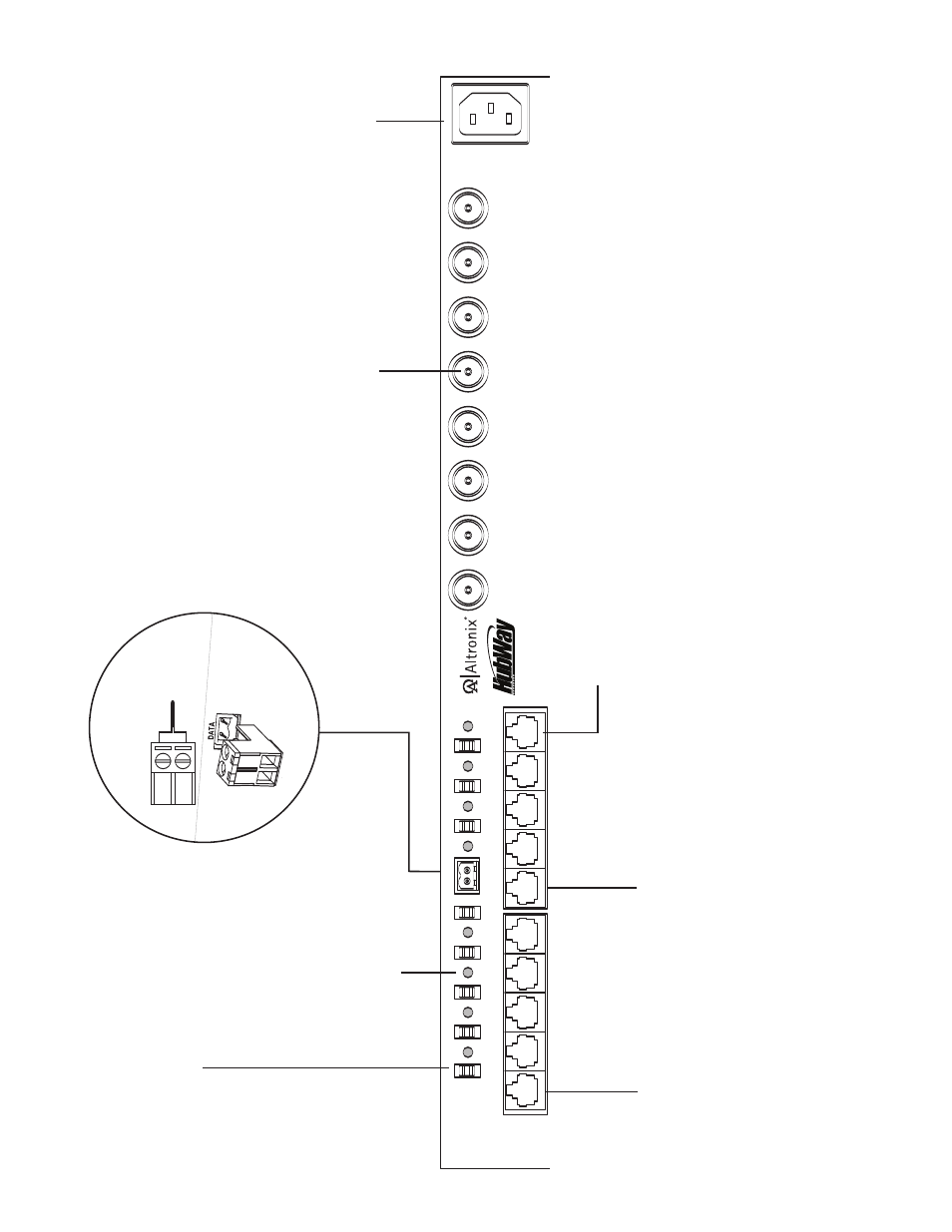
HubWay Passive Unit
A
C
P
O
W
ER
8
7
6
5
4
3
2
1
24
VA
C
O
FF
28
VA
C
--
D
AT
A
+
1
2
3
4
5
6
7
8
C
H
1
-4
C
H
5
-8
1-
8
1g
- Channels 1-8:
CA
T
-5
or higher str
uctured
cab
le to
V
ideo/Balun Combiners at cameras 1-8.
When linking HubW
ay UTP
T
ranscei
v
er Hubs
to HubSat Remote
Accessor
y Modules,
an
y of these jacks will f
acilitate
data
transmission
for
PTZ control.
1d
- BNC Connector:
V
ideo
outputs to head end
equipment (D
VR).
1a
- Output v
olta
g
e switc
hes:
Selects
24V
A
C/28V
A
C/OFF
for each output.
1f
- Channels 1-4 & Channels 5-8:
Links
HubSat units enab
ling video transmis
-
sion of up to four (4) cameras o
v
er a single
CA
T
-5 str
uctured cab
le.
1e
- IEC 320 Connector:
115V
A
C
60Hz (g
rounded line
cord included).
F
ig
. 1
1c
- Data:
Remo
v
ab
le
ter
minal
b
locks for RS422/
RS485 input from head end
equipment (D
VR) for PTZ control.
+ --
D
a
ta
i
n
p
u
t
fr
o
m
H
e
a
d
E
n
d
E
q
u
ip
m
e
n
t
(D
V
R
).
T
o
p
V
ie
w
1b
- LED(s) 1-8:
P
o
w
er
indicators.
Rear
- NetWay3012 Installation Instructions (2 pages)
- HubWay 16Di Data Sheet (2 pages)
- Maximal77 Installation Instructions (20 pages)
- HubWay Dvi Data Sheet (1 page)
- HubWay Av2 Data Sheet (1 page)
- PD4CB Installation Instructions (1 page)
- ACM4CB Data Sheet (2 pages)
- VertiLine63D Data Sheet (2 pages)
- eBridge16CR Installation Instructions (8 pages)
- LPS3WP12 Data Sheet (2 pages)
- VertiLine246D Data Sheet (2 pages)
- T24130D Data Sheet (1 page)
- eBridge1PCRTX Data Sheet (2 pages)
- RB5 Installation Instructions (1 page)
- Tempo2 Data Sheet (1 page)
- BC600G Data Sheet (1 page)
- eBridge1CRT Data Sheet (2 pages)
- AL400ULB Data Sheet (1 page)
- PT2724 Installation Instructions (8 pages)
- OLS180 Installation Instructions (2 pages)
- HubWay 8CD Data Sheet (2 pages)
- AL175ULB Data Sheet (1 page)
- StrikeIt2 Installation Instructions (8 pages)
- LPD Data Sheet (1 page)
- eBridge4SK Installation Instructions (8 pages)
- LPS3AC Installation Instructions (2 pages)
- T2428100 Data Sheet (1 page)
- TP1650 Data Sheet (1 page)
- T2885D Data Sheet (1 page)
- T2428175 Installation Instructions (1 page)
- T1656 Installation Instructions (1 page)
- SMP3 Data Sheet (1 page)
- RBR1224 Data Sheet (1 page)
- HubWay LD16D Data Sheet (2 pages)
- eFlow102NX16D Installation Instructions (16 pages)
- T24175C Data Sheet (1 page)
- Maximal5D Data Sheet (2 pages)
- Maximal7 Installation Instructions (16 pages)
- HubWay 8CDS Data Sheet (2 pages)
- eFlow4NX8D Installation Instructions (16 pages)
- MOM5C Data Sheet (1 page)
- eBridge16PCRX Installation Instructions (8 pages)
- HubWay EX16SP Data Sheet (2 pages)
- T24130C Installation Instructions (1 page)
- Maximal5 Data Sheet (2 pages)